
Circuit Diagram
Index 122
Low-Sensitivity Sallen-Key Filter Design with the HP-41C/CV/CX Programmable Calculator
Published:2013/5/7 21:51:00 Author:muriel | Keyword: Low-Sensitivity, Sallen-Key Filter, HP-41C/CV/CX Programmable Calculator

View full Circuit Diagram | Comments | Reading(723)
homemade "ColdHeat"
Published:2013/5/7 21:50:00 Author:muriel | Keyword: homemade "ColdHeat"

View full Circuit Diagram | Comments | Reading(1269)
Fish Caller 2
Published:2013/5/7 21:48:00 Author:muriel | Keyword: Fish Caller

View full Circuit Diagram | Comments | Reading(1059)
Electro-Static Air Filters
Published:2013/5/7 21:46:00 Author:muriel | Keyword: Electro-Static Air Filters

View full Circuit Diagram | Comments | Reading(2080)
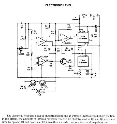
Electronic level
Published:2013/5/7 21:45:00 Author:muriel | Keyword: Electronic level
View full Circuit Diagram | Comments | Reading(0)
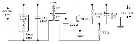
5W INVERTER
Published:2013/5/7 21:40:00 Author:muriel | Keyword: 5W INVERTER
View full Circuit Diagram | Comments | Reading(598)
SOUND TRIGGERED FLASH
Published:2013/5/7 21:39:00 Author:muriel | Keyword: SOUND TRIGGERED FLASH
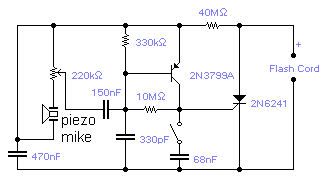
If you wish to take a picture of a fleeting event which generates a sound, you can do it with this sound activated trigger. It does not require any power supply: it feeds on the high voltage available on the flash trigger terminal. Any economic ceramic microphone is suitable for the purpose. The 68nF capacitor introduces a small delay in the operation of the flash and may help in getting the picture in exactly the right moment although you should expect to take several shots for best results. With this circuit you will be able to catch a cork leaving the champagne bottle or the moment a balloon is punctured. The whole circuit could be assembled in the mike housing making a very compact device. (View)
View full Circuit Diagram | Comments | Reading(0)
SCR INVERTER
Published:2013/5/7 21:38:00 Author:muriel | Keyword: SCR INVERTER
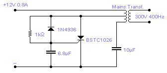
The only drawback with this circuit is that it might latch in the conducting state if the load is too heavy or if there is a short at the output, this requires some kind of protection, on the input line, in the form of a fuse or similar. The transformer used is a 10W mains type with 6V+6V windings on the SCR side and a 110V+110V windings, in series, at the output. Efficiency is 50% and the ideal load is equivalent to a 22k resistor, 5W. The output waveform is vaguely sinusoidal at a frequency of 400Hz. (View)
View full Circuit Diagram | Comments | Reading(1949)
ELECTRIC FIELD DETECTOR
Published:2013/5/7 21:38:00 Author:muriel | Keyword: ELECTRIC FIELD DETECTOR
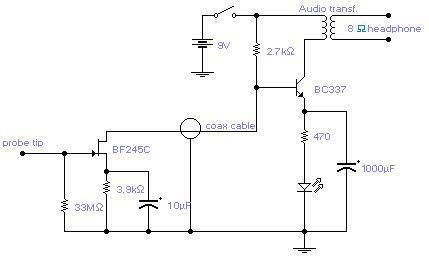
The circuit will come handy when you have to follow the mains wires buried in the wall or even water pipes provided they are not too far away (2-4cm max). It will also detect a conversation on a telephone cable without actually touching it (for testing purposes only) and it works as a microphone if you keep a plastic kitchen foil between the probe tip and your mouth. The probe is just the 12mm long gate lead of the transistor. The 33M resistor should be cut short and soldered where the lead enters the transistor case. Connection to the other part of the circuit is via a standard coaxial cable of any length. The input is not protected and a pair of low leakage diodes (JPAD5) could be connected back to back between gate and ground. I did not find them necessary: I covered, with a small piece of plastic sponge, the probe tip to avoid direct contact with electrified surfaces and used a minimum of care when handling the probe. (View)
View full Circuit Diagram | Comments | Reading(2126)
ULTRA LOW FREQUENCY RECEIVER
Published:2013/5/7 21:37:00 Author:muriel | Keyword: ULTRA LOW FREQUENCY RECEIVER

The frequency covered is from 0.1Hz to 10Hz and useful signals are received up to 16Hz. The first Op-Amp, properly shielded, must be installed close to the antenna (1-3m long) and connected to the rest of the circuit with a 5-core shielded cable. Adjust the 100k trimmer so that the DC setting at the output of the OPA124 does not change when turning the 220k sensitivity pot. A low pass filter followed by a notch filter take care of the mains induced noise. The values in brackets are good for a 60Hz mains. 1% components should be used for the 3 resistors and 3 capacitors of the notch filter. A voltage controlled oscillator gives an audible frequency that follows the input signal and it is very handy if the unit is made portable although I found that just walking around is enough to bury the signal being received. The output signal goes first to a meter and then is available for the connection to a data logger, which is an almost essential part of the receiver. Sensitivity is quite adequate: any TV set switching on in the area will be detected. There are also a host of other mysterious signals of unknown origin. The input protection diodes are special low leakage type and should not be replaced by standard diodes. These diodes can be dispensed with if the antenna is installed with care and away from strong electric fields. The diodes connected to the meter are Schottky diodes and will provide a bias against very small signals (mostly noise) which will not go through to the data logger. Pin connection for OPA124: 1 and 5: DC set, 2 and 3: inverting and non-inverting, 6: output, 8: substrate. Pin connection for LF412: 2 and 3: inverting and non-inverting, 1: output, 6 and 5: inverting and non-inverting, 7: output. (View)
View full Circuit Diagram | Comments | Reading(1982)
220V MAINS MONITOR
Published:2013/5/7 21:36:00 Author:muriel | Keyword: 220V MAINS MONITOR

View full Circuit Diagram | Comments | Reading(1122)
ZENER OSCILLATORS
Published:2013/5/7 21:36:00 Author:muriel | Keyword: ZENER OSCILLATORS
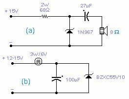
These two circuits are interesting from an academic point of view. Their practical implementation is rather critical and it is not easy to get steady operation. Circuit (a) requires a cooked zener: connect it first to a constant current generator, then increase the current until the voltage across the zener starts to decrease. Reduce the supply current and wait a few minutes until it really warms up. The zener is now ready for the circuit: increase the voltage slowly until it oscillates (1KHz in the circuit shown). You may need to decrease the voltage once oscillation takes place. With suitable circuit components it will oscillate up to 20MHz. Circuit (b) will oscillate at a very low frequency, normally 2-5Hz, provided the voltage is increased very slowly, loading is critical and you may find that a slightly different lamp will work better. Higher voltage zeners work better than low voltage zeners and the circuits operate only with the specified types. The reasons for the oscillations are unknown, although, for circuit (b) it is felt that some kind of reversible thermal breakdown is at work. (View)
View full Circuit Diagram | Comments | Reading(710)
SCR OSCILLATOR
Published:2013/5/7 21:35:00 Author:muriel | Keyword: SCR OSCILLATOR
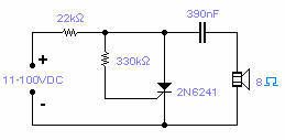
Silicon controlled rectifiers (SCR) can easily oscillate if there is an inductor (a speaker coil in this case) which gives just enough extra voltage to completely switch off the sustain current. In this way a new cycle may start and oscillations set in. It operates over a wide range of supply voltage and components values are not critical at all. Operational frequency in this circuit goes from 100Hz at 11V to 10KHz at 100V (View)
View full Circuit Diagram | Comments | Reading(1142)
POWER FLASHER 2
Published:2013/5/7 21:33:00 Author:muriel | Keyword: POWER FLASHER
There is no need to resort to complex circuitry if what you are looking for is a simple power flasher. The light will flash at around 1Hz with a 100W bulb at a duty cycle of 50%. The max. load that can be driven with this circuit is 200W and if you wish to have a different frequency you have to change the value of the capacitor. Operation at 110VAC has not been tested although I expect it to work provided the resistors are set at about half the stated value. The SCR is manufactured by Siemens but any other equivalent semiconductor, with standard gate sensitivity, should work fine. WARNING! - This circuit is directly connected to the mains and proper safety precautions should be taken. A more modern design would use a sensitive gate SCR, other low power resistors and a 10μF, 250V electrolytic capacitor. (View)
View full Circuit Diagram | Comments | Reading(1632)
TELEPHONE LINE MONITOR
Published:2013/5/7 21:31:00 Author:muriel | Keyword: TELEPHONE LINE MONITOR

If you feel that somebody is tampering with your telephone line you might find this little circuit useful. It detects if there is another telephone connected to the line, if there is a short or an open line. Sound and a flashing light will tell you which is the current situation. The speaker is practically cut out during a normal conversation thus preserving privacy, only the LED will flash occasionally. The circuit does not require any battery and takes the supply from the telephone line itself. The transistors used are wired in a reversed biased fashion thus behaving as oscillators. You might try the 2N2222A as an alternative (not tested, you may need to increase the zener to 10V for the 2N2222A). This monitor is, of course, suitable only for analogue lines. Watch the polarity of the input line: the circuit will not be damaged by a polarity reversal but it will not operate correctly. (View)
View full Circuit Diagram | Comments | Reading(1690)
ELECTRONIC ATTENUATOR
Published:2013/5/7 21:30:00 Author:muriel | Keyword: ELECTRONIC ATTENUATOR
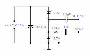
Two low voltage, low power zeners are used to control electronically the level of an audio signal. The attenuation range is from 6 to 58dB for an input current from 0.042 to 77mA corresponding to a control voltage from 2.7 to 7.5V. If control voltage is limited to 5V, the attenuation is around 30dB at a control current of 2mA. This is not an HiFi attenuator but might come useful as a general purpose audio attenuator. (View)
View full Circuit Diagram | Comments | Reading(705)
SEISMIC DETECTOR
Published:2013/5/7 21:30:00 Author:muriel | Keyword: SEISMIC DETECTOR

The piezoelectric element of a kitchen gas lighter is used in this simple, yet effective seismic detector. The piezo element must be placed vertically, one end solidly to ground. A 2-3 pound weight of fine gravel in a loose package should be placed on top at the other end. The high voltage lead goes to the IC, placed close to the piezo element. The whole box is acoustically and electromagnetically screened. A 3 core shielded cable brings the signal to the rest of the circuit and to the power supply (+/- 15V). The SB140 diodes are Schottky type and pin 8 (substrate) of the IC should be connected to ground. (View)
View full Circuit Diagram | Comments | Reading(1301)
REVERSE BIAS OSCILLATOR
Published:2013/5/7 21:29:00 Author:muriel | Keyword: REVERSE BIAS OSCILLATOR
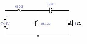
There are a number of npn transistors that will oscillate in the audio range when reverse biased. Minimum supply voltage is 7V for low power transistors such as BC109, BC238 and 2N2222A (about 10V for the latter), it becomes 12V for medium power transistors such as BD139 and is 16V for power transistors as BUX22 and 2N6543. Current drain is 4mA at 9V and frequency of oscillation is 550Hz. The base is normally left open. (View)
View full Circuit Diagram | Comments | Reading(604)
GEOMAGNETIC FIELD DETECTOR
Published:2013/5/7 21:29:00 Author:muriel | Keyword: GEOMAGNETIC FIELD DETECTOR

This basic oscillator will detect the Earth magnetic field. The ferrite rod and coil are taken from an old Medium Wave receiver and a small magnet is glued at one end. Tune to a medium wave commercial station until you hear a beat note. Any movement of the ferrite rod will produce an audible note that depends on the prevailing Earth magnetic field. Screening is essential. Use a plastic box padded, on the inside, with copper wires running parallel to the rod and grounded in one place only. A small hole is made in the box in order to adjust the trimmer capacitor with a plastic screwdriver. An American equivalent to the BC337 could be the 2N2369A but I did not try it out. (View)
View full Circuit Diagram | Comments | Reading(1098)
MULTIPLE LED FLASHER
Published:2013/5/7 21:28:00 Author:muriel | Keyword: MULTIPLE LED FLASHER

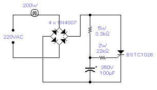
This circuit will flash a string of LED's, typically 16, with direct connection to the mains and with a period adjustable between 1 and 4 seconds depending on the setting of the 22K/1W pot. Operation at 110V should also be possible but has not been tested. It can be used as a Christmas Tree decoration, entertainment in general or to flash a symbol made out of LED's - WARNING - this circuit is implemented at your own riisk! It operates directly out of the mains and proper precautions must be taken. (View)
View full Circuit Diagram | Comments | Reading(0)
| Pages:122/2234 At 20121122123124125126127128129130131132133134135136137138139140Under 20 |
Circuit Categories
power supply circuit
Amplifier Circuit
Basic Circuit
LED and Light Circuit
Sensor Circuit
Signal Processing
Electrical Equipment Circuit
Control Circuit
Remote Control Circuit
A/D-D/A Converter Circuit
Audio Circuit
Measuring and Test Circuit
Communication Circuit
Computer-Related Circuit
555 Circuit
Automotive Circuit
Repairing Circuit