© 2008-2012 SeekIC.com Corp.All Rights Reserved.
Signal Processing
ULTRA LOW FREQUENCY RECEIVER
Published:2013/5/7 21:37:00 Author:muriel | Keyword: ULTRA LOW FREQUENCY RECEIVER | From:SeekIC

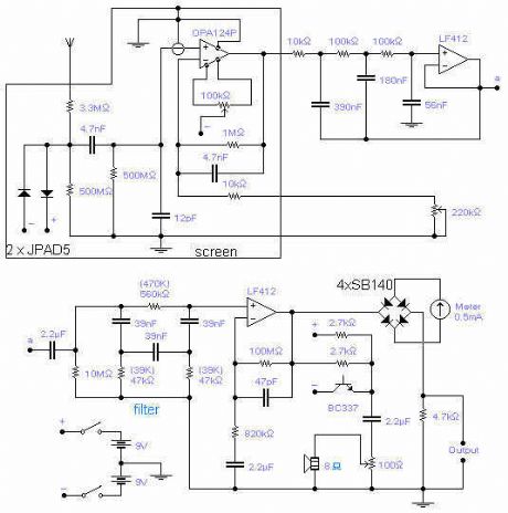
The frequency covered is from 0.1Hz to 10Hz and useful signals are received up to 16Hz. The first Op-Amp, properly shielded, must be installed close to the antenna (1-3m long) and connected to the rest of the circuit with a 5-core shielded cable. Adjust the 100k trimmer so that the DC setting at the output of the OPA124 does not change when turning the 220k sensitivity pot. A low pass filter followed by a notch filter take care of the mains induced noise. The values in brackets are good for a 60Hz mains. 1% components should be used for the 3 resistors and 3 capacitors of the notch filter. A voltage controlled oscillator gives an audible frequency that follows the input signal and it is very handy if the unit is made portable although I found that just walking around is enough to bury the signal being received. The output signal goes first to a meter and then is available for the connection to a data logger, which is an almost essential part of the receiver. Sensitivity is quite adequate: any TV set switching on in the area will be detected. There are also a host of other mysterious signals of unknown origin. The input protection diodes are special low leakage type and should not be replaced by standard diodes. These diodes can be dispensed with if the antenna is installed with care and away from strong electric fields. The diodes connected to the meter are Schottky diodes and will provide a bias against very small signals (mostly noise) which will not go through to the data logger. Pin connection for OPA124: 1 and 5: DC set, 2 and 3: inverting and non-inverting, 6: output, 8: substrate. Pin connection for LF412: 2 and 3: inverting and non-inverting, 1: output, 6 and 5: inverting and non-inverting, 7: output.
Reprinted Url Of This Article:
http://www.seekic.com/circuit_diagram/Signal_Processing/ULTRA_LOW_FREQUENCY_RECEIVER.html
Print this Page | Comments | Reading(3)

Article Categories
power supply circuit
Amplifier Circuit
Basic Circuit
LED and Light Circuit
Sensor Circuit
Signal Processing
Electrical Equipment Circuit
Control Circuit
Remote Control Circuit
A/D-D/A Converter Circuit
Audio Circuit
Measuring and Test Circuit
Communication Circuit
Computer-Related Circuit
555 Circuit
Automotive Circuit
Repairing Circuit
New published articles
Response in 12 hours

Code: