Basic Circuit
PIEZOELECTRIC TRANSFORMER
Published:2013/5/7 21:23:00 Author:muriel | Keyword: PIEZOELECTRIC TRANSFORMER | From:SeekIC

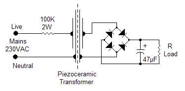
If there is a need to feed very low power devices you may resort to infrared optocouplers, solar cells, batteries or low power transformers although the latter might be rather oversized for the intended purpose. Eventually, with the exception of solar cells, all of them draw power from the mains so it might be convenient to use a piezoelectric transformer if the power required is in the range 0.1 to 0.3 mW. The schematic shows an easy implementation of such a transformer. Two piezoceramic sounders are glued back-to-back so that the mechanical movement of the first, the primary, is transferred to the second, the secondary. The ac output voltage can be used as it is or rectified in order to feed micropower electronic equipment or trickle charge small backup batteries. The actual implementation requires two ceramic sounders with high intrinsic capacitance: sounders with 80 to 110nF are readily available and usually come as 50mm discs. Two of these discs are cut down to 35mm in order to have a more compact unit and a lower stray capacitance between primary and secondary. A layer of double-sided adhesive tape is laid on the larger plate of each sounder in order to assure proper electrical insulation between primary and secondary. The sides of the sounders are then pressed against each other and the transformer is ready to operate.
R Load
VAC
VDC
100 KΩ
5.1
4.67
47 KΩ
4.22
3.29
22 KΩ
2.77
2.06
10 KΩ
1.41
1.1
4.7 KΩ
0.68
0.56
The table shows the measured output under several loading conditions: the ac output was measured with the load directly across the output terminals while the dc output was measured with a full wave rectifier in place. The measured dc voltage refers to a schottky bridge rectifier but the use of standard 1N4004 diodes will only show a modest 6-8% voltage decrease. Measurements were taken with the transformer operating in free air, without any holder, but a proper mechanical layout would require the transformer to be firmly held by the edge of the disc. The use of a plastic box is mandatory for safety reason and improves the transfer of mechanical energy to the secondary thus obtaining a 15-20% voltage increase.
Reprinted Url Of This Article:
http://www.seekic.com/circuit_diagram/Basic_Circuit/PIEZOELECTRIC_TRANSFORMER.html
Print this Page | Comments | Reading(3)

Article Categories
power supply circuit
Amplifier Circuit
Basic Circuit
LED and Light Circuit
Sensor Circuit
Signal Processing
Electrical Equipment Circuit
Control Circuit
Remote Control Circuit
A/D-D/A Converter Circuit
Audio Circuit
Measuring and Test Circuit
Communication Circuit
Computer-Related Circuit
555 Circuit
Automotive Circuit
Repairing Circuit
Code: