Control Circuit
LONG DELAY TIMER 2
Published:2013/5/7 21:16:00 Author:muriel | Keyword: LONG DELAY TIMER | From:SeekIC

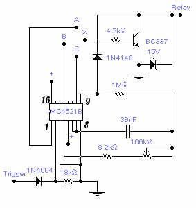
A max. delay of 20 hours is achieved by this relatively simple circuit. A permanent ground, or no signal, at the trigger input starts the timer. A ground at the relay output is available after a set time that depends on the connection of the transistor base (X) to one of the counter output: connection with (C) gives a min. delay of 1m 40s and max. of 18m 30s. Connection with (B) gives a min. delay of 13m 20s and max. of 2h 28m. Connection with (A) gives a min. delay of 1h 47m and max. of 20h. Supply voltage is between 6 and 15V and longer delay could be obtained by increasing the capacitor value up to 10 times with a delay in excess of 1 week. A positive at the trigger input will reset the counter. Adjust the 100K pot. for the desired timing. The load is typically a relay but any load with a max. current of 200 mA will work fine. Admittedly this is not a very original circuit but can save some time if you need to build one. The IC is a Cmos 24-stage binary counter MC4521B from Fairchild, or alternatively, you may use the MC14521B from Motorola.
Reprinted Url Of This Article:
http://www.seekic.com/circuit_diagram/Control_Circuit/LONG_DELAY_TIMER_2.html
Print this Page | Comments | Reading(3)

Article Categories
power supply circuit
Amplifier Circuit
Basic Circuit
LED and Light Circuit
Sensor Circuit
Signal Processing
Electrical Equipment Circuit
Control Circuit
Remote Control Circuit
A/D-D/A Converter Circuit
Audio Circuit
Measuring and Test Circuit
Communication Circuit
Computer-Related Circuit
555 Circuit
Automotive Circuit
Repairing Circuit
Code: