
Signal Processing
Index 190
Clapp signal generator
Published:2011/4/18 20:11:00 Author:Ecco | Keyword: Clapp , signal generator
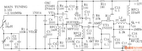
The clapp signal generator is shown in the chart. VTl isa variable LC oscillator composed of the typical clapp circuit in high stability. The feedback factor is decided by the capacitors C4、C5, and their capacitance is so high that it can effectively reduce the short-term fibrillation rate drift caused by the changing of capacitance when starting up.
(View)
View full Circuit Diagram | Comments | Reading(786)
0.1Hz~500kHz signal source made by LM567
Published:2011/4/18 20:12:00 Author:Ecco | Keyword: 0.1Hz~500kHz, signal source
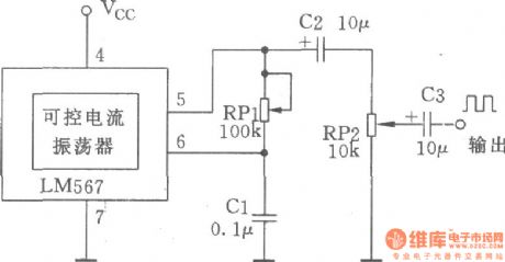
The manifold block LM567 is a stable PLL circuit with synchronous amplitude locking and detecting. The internal manifold controllable current oscillator can make a simple small adjustable low-frequency signal source, it's very easy for maintenance. Circuit is as shown in the chart.
(View)
View full Circuit Diagram | Comments | Reading(1584)
Voltage-controlled sinusoidal oscillator composed of MC1046B
Published:2011/4/18 20:10:00 Author:Ecco | Keyword: Voltage-controlled , sinusoidal , oscillator
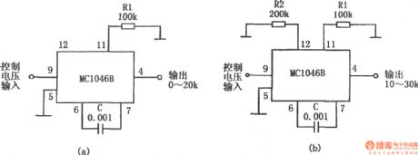
The voltage-controlled sinusoidal oscillator circuit is shown in the chart. It is composed of MC1046B. When the controlling input voltage is 0 ~ 5V, the outputcan get the sine signal withfrequencyfrom 0 ~ 20kHz.The frequency range is decided by the resistor R1 and capacitor C, changing the resistors and capacitorscould change the oscillation frequency. If the external resistor R2 connects topin 12 , oscillation frequency range could be changed. If you choose R2 = 2R1, the oscillation frequency becomes 10 ~ 30kHz.
(View)
View full Circuit Diagram | Comments | Reading(1032)
Bell ringing signal generator
Published:2011/4/18 20:09:00 Author:Ecco | Keyword: bell ringing , signal generator
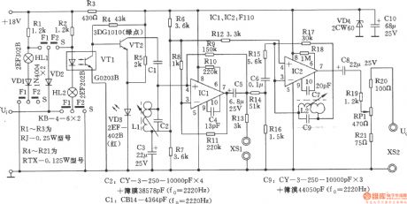
Bell ringing signal generator is generally used as calling signal source of communications equipment. Calling sending oscillator can send shift frequency calling signal under the control of automatic switching system, to choose the user for opposite person. Klingel signal generator is composed of shift frequency control circuit, LC shift frequency oscillator, output circuit, the circuit is shown as the chart.
(View)
View full Circuit Diagram | Comments | Reading(871)
The voltage-controlled oscillator with triangular wave and square wave output
Published:2011/4/18 1:59:00 Author:Ecco | Keyword: voltage-controlled oscillator , triangular wave , square wave , output
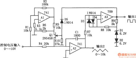
The voltage-controlled oscillator with triangular wave and square wave output is shown as the chart. The circuit is a controlled voltage-controlled oscillator. It has good stability and excellent linearity and a wide frequency range. The circuit has two output terminals, one is the square wave output, and the other one is the triangle wave output. In the figure, A1 is an inverter, A2 is an integrator, A3 is a comparator. The FET Q1 is used to transform integration direction. The reference voltage of comparator is provided by diode D1, D2, The comparing between the output of integrator and reference voltage make the square-wave output. Resistors R5, R6 are used to reduce the drain voltage of Q1 to ensure a large input signal Q1 being fully closed. Resistors R7, R8, and diodes D3, D4 A3 are used to prevent blocking. According to the value of marked components in the figure, the power supply is +15V, the transform coefficient is the 1kHz / V. The circuit has a linearity error less than ± 0.5% in the frequency range of 100:1.
(View)
View full Circuit Diagram | Comments | Reading(1550)
Sine wave generator composed of inverter
Published:2011/4/18 2:27:00 Author:Ecco | Keyword: Sine wave generator , inverter

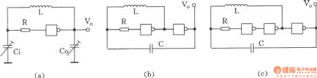
The sine wave generator composed of inverter is shown as the chart. The circuit could get high stable sine wave in more than a few MHz. In the figure, A1 and the crystal oscillator form a oscillating circuit, the output of A1 becomes sine wave signal after passing the buffer A2. In the circuit, A1 is linear amplifier, the whole circuit is in amplifying state. As the characteristics of the crystal oscillator are different, the output frequency and voltage are different, and R2 is used to adjust waveform. For getting ccurate oscillation frequency, it can connect a variable capacitor on two ports of capacitor C1 in parallel. Oscillation frequency of the circuit is decided by crystal oscillator, it can change the output signal frequency.
(View)
View full Circuit Diagram | Comments | Reading(1987)
The adjustable voltage-controlled oscillator with large duty cycle
Published:2011/4/18 1:28:00 Author:Ecco | Keyword: adjustable, voltage-controlled oscillator , large duty cycle
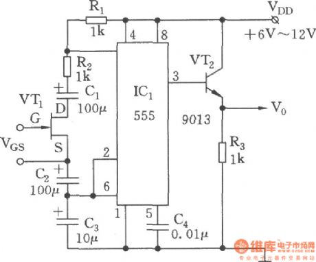
Voltage-controlled oscillator circuit is as shown. 555, R1, R2, C1 ~ C3 and VT1 form a voltage-controlled multivibrator, FET (JFET) VT is voltage-controlled resistor, which can change the impedance between VT-drain (D) and source (S) by changing the gate-source voltage VGs. The coupled capacitors C1、C2 are connected to D,S of VT, they are used to prevent the influence from rest of the circuit of the DC voltage on the JFET. If making coupling capacitors have no effect on the charging and discharging time of time base circuit, the size of C1, C2 should be 10 times of the timing capacitor C3. The advantages of this circuit: the changing of gate-source voltage VGs can make an adjustable variable resistor Rx (can be as large as several hundred kΩ), then it gets the changing of duty cycle and the cycle.
(View)
View full Circuit Diagram | Comments | Reading(2626)
Voltage controlled oscillator with Vc-side controlling duty cycle
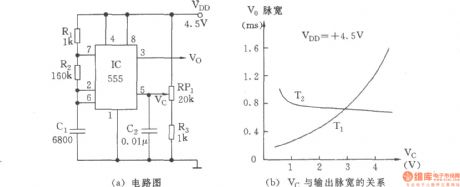
Published:2011/4/18 0:54:00 Author:Ecco | Keyword: Voltage controlled oscillator , Vc-side, controlling , duty cycle
View full Circuit Diagram | Comments | Reading(539)
The multivibrator circuit with variable pitch
Published:2011/4/18 0:40:00 Author:Ecco | Keyword: multivibrator , variable pitch
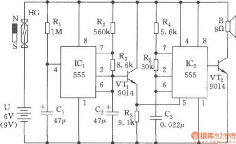
The multivibrator circuit with variable pitch is composed of two 555 time base circuits, it can issue wave of oscillation changed in 400~2500Hz, and its sound is similar to the sound of the public security police. The circuit consists of power-delay, low-frequency oscillator and the modulation generator.
(View)
View full Circuit Diagram | Comments | Reading(729)
FM waveform generator
Published:2011/4/17 22:14:00 Author:Ecco | Keyword: FM , waveform generator

The circuit shown in Figure is the FM waveform generator which can generate 220kHz FM waveform. The internal regulator of CD40468 provides a stable supply voltage for the operational amplifier CA3140, the rated voltageis 5.4V, R5is the current limiting resistor forregulator.
(View)
View full Circuit Diagram | Comments | Reading(960)
General-purpose function generator
Published:2011/4/17 20:52:00 Author:Ecco | Keyword: general-purpose , function generator
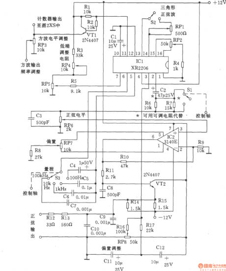
Signal generator can be divided into three parts: the sine wave and triangle wave generator, counter and pulse and ramp generator. The circuit is as shown, XR2206 adopts voltage controlled oscillator, the frequency adjustment is achieved by potentiometer RP5 (10k), it is easy to adjust to the frequency in one-thousandth. If you change the resistance of the fixed resistor R3, the resistance of the RP5 could also be changed. Sine and triangular waves is different from other similar instruments, the attenuator switch Sl only can change the magnitude of signal, it does not affect the bias voltage. According to the need, the fixed attenuation can be got (to 20dB, the voltage ratio is 10), it adjusted by R6, fixed resistor R7 connecting in parallel. It also could connect to rheostat to adjust resistance. Although the adjustment of resistance is more expensive, but it is easy to implement.
(View)
View full Circuit Diagram | Comments | Reading(3358)
Linear vco(8038、μA741)
Published:2011/4/14 22:46:00 Author:Ecco | Keyword: Linear , vco
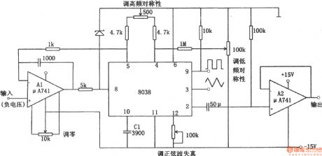
The linear voltage-controlled oscillator circuit is shown as the chart. In the figure, A1 is a constant current source circuit which is used to improve charging and discharging characteristics of C1. It makes a linear relationship between the output frequency and the input control voltage. A2 is a sine wave output buffer. If inputting the low-frequency sawtooth to the control voltage terminal, the circuit will become a linear sweep generator. But putting a signal voltage on input terminal will make the circuit output frequency modulation wave. The circuit can be used as an A / D converter changing a digital signal into the voltage with a frequency counter counting the output. Linear VCO is also known as V / F converter. (View)
View full Circuit Diagram | Comments | Reading(3716)
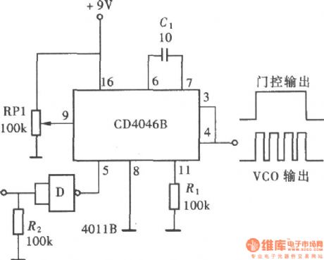
The quantitative pulse exported by CD4046
Published:2011/4/14 2:34:00 Author:Ecco | Keyword: quantitative pulse
View full Circuit Diagram | Comments | Reading(612)
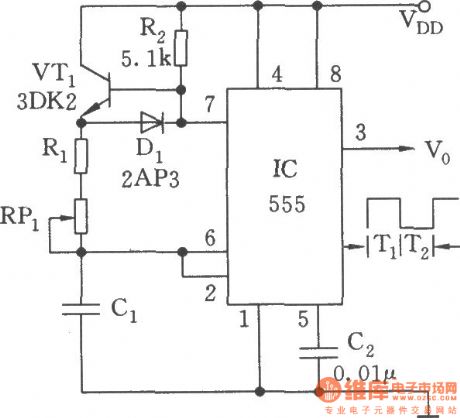
RF driver audio oscillator
Published:2011/4/14 3:24:00 Author:Ecco | Keyword: RF driver, audio oscillator
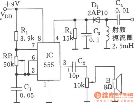
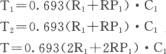
As shown, 555 and Rl, RPl, C1 and other components form controllable audio oscillator, f = 1.44 / (R1 +2 RP1) C1, the frequency of parameter in the diagram is between 600Hz ~ 20kHz, it can be adjustedby RP1.
(View)
View full Circuit Diagram | Comments | Reading(631)
Data-controlled variable frequency oscillator
Published:2011/4/14 3:25:00 Author:Ecco | Keyword: Data-controlled, variable frequency , oscillator
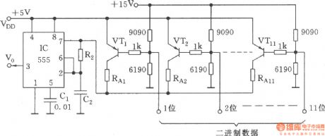
As shown, toaccess 11-bit binary data(highlevel is 1 , low level is 0 )on the base bias circuit of VT1~VT11, there are 2048 combinations. When one pointis in low level, the corresponding VT tube is conducted, the C2 charges through the RA + R2. RAis the equivalent resistance of the resistor connecting to each conducting tube.
(View)
View full Circuit Diagram | Comments | Reading(567)
Multivibrator with symmetric wave output
Published:2011/4/14 3:40:00 Author:Ecco | Keyword: Symmetric wave , output, multivibrator
The chart is as shown. Comparing with the general multivibrator, it adds a biased transistor VT1 to the charging circuit. VT1 can be fully conducted in the effect of R2; When C1 discharges, it will be completely closed. As the forward resistance is low(less than hundreds ohm) when VT1 switch and germanium diode arein the conducting state, it has little influence on charging and discharging time.
Another advantage of this circuit is thatthe loading change has a minimal impact on the output voltage amplitude, duty cycle and oscillation frequency. (View)
View full Circuit Diagram | Comments | Reading(571)
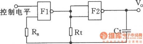
The controlled oscillator composed of Nand gate
Published:2011/4/7 3:32:00 Author:Ecco | Keyword: controlled oscillator, NOT gate
View full Circuit Diagram | Comments | Reading(522)
LC oscillator composed of NAND gate
Published:2011/4/7 3:32:00 Author:Ecco | Keyword: LC oscillator , NAND gate
View full Circuit Diagram | Comments | Reading(1461)
Wien oscillator regulator
Published:2011/4/14 2:52:00 Author:Ecco | Keyword: wien , oscillator , regulator
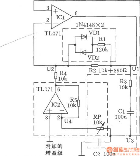
In the Wien bridge, to change any resistance will change the frequency and attenuation. As shown, by adjusting the resistance can change the gain of the amplifier and compensate for the attenuation.
(View)
View full Circuit Diagram | Comments | Reading(510)
Simple multi-harmonic generator
Published:2011/4/14 2:39:00 Author:Ecco | Keyword: Simple , multi-harmonic generator
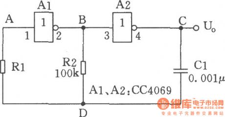
Thecircuit shown in the chart is a multi-harmonic generator circuit which is comprised of hex inverter CC4069 and so on. The circuit is suitable for low-frequency clock oscillation circuit which are less strict for frequency stability and accuracy. (View)
View full Circuit Diagram | Comments | Reading(560)
| Pages:190/195 At 20181182183184185186187188189190191192193194195 |
Circuit Categories
power supply circuit
Amplifier Circuit
Basic Circuit
LED and Light Circuit
Sensor Circuit
Signal Processing
Electrical Equipment Circuit
Control Circuit
Remote Control Circuit
A/D-D/A Converter Circuit
Audio Circuit
Measuring and Test Circuit
Communication Circuit
Computer-Related Circuit
555 Circuit
Automotive Circuit
Repairing Circuit