
Signal Processing
Index 189
CMOS Gate voltage-controlled oscillator
Published:2011/4/14 2:33:00 Author:Ecco | Keyword: CMOS, Gate , voltage-controlled oscillator
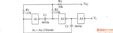
In the circuit that as shown in the chart, the free-running multivibrator is composed of two NOT gates of A1 and A2. With the changing of external control voltage Vcc, the circuit oscillation frequency will change. When the value of VCC is near the threshold of gate,it has the least impact on charging and discharging of RC. The greater deviation between VCC and threshold of gate, the capacitor charges and discharges faster, so the oscillation frequency of the circuit is more resistant.
(View)
View full Circuit Diagram | Comments | Reading(714)
The self-excited multivibrator composed of CC4093
Published:2011/4/19 6:47:00 Author:Ecco | Keyword: self-excited , multivibrator
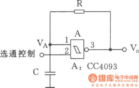
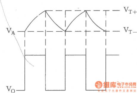
It needs a resistance and a capacitor connecting externally when forming a multivibrator by Schmidt trigger. The circuit is used to the low frequency vibration source which has lower demand for accuracy, and the vibration is controlled. The circuit in the figure is a self-excited much harmonic oscillator composed of four 2 input Schmidt trigger.
(View)
View full Circuit Diagram | Comments | Reading(538)
450 Audio signal generator
Published:2011/4/19 2:54:00 Author:Ecco | Keyword: Audio, signal , generator
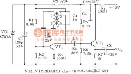

The oscillator is the services signal source for communication user . Working principle is as shown. It consists of VTl, VT2, and other related components. VTl using transformer T to couple oscillation signal, VT2 is the common collector buffer amplifier circuit, the emitter output. T transformer with 1-4 winding and the capacitor C4 form a selecting frequency network. In order to prevent magnetic saturation of T, T is connected to the collector of VTl by the 1-2 tap, 5-6 of T is the feedback loop. Detection: The DC-bit of pin-to-ground (reference value) is as shown in the table.
(View)
View full Circuit Diagram | Comments | Reading(422)
3-1 count down circuit composed of CD4013
Published:2011/4/19 4:37:00 Author:Ecco | Keyword: 3-1 , count down circuit

In digital circuits, sometimes it needs pulse a divider circuit which could minus a few input pulse. The appropriate combination ofCD4013 and feedback door can achieve any pulse subtraction circuit. Figure 3-1 shows 3-1 count down circuit composed of CD4013.
(View)
View full Circuit Diagram | Comments | Reading(1835)
24V DC 220V AC 100W push pull chopper
Published:2011/4/19 3:16:00 Author:May | Keyword: 24V DC, 220V AC, 100W, push pull, chopper
24V DC power supply (such as storage battery) can offer power to this circuit. Controlled by chopper, it can output 220V, 50Hz AC. The main technical data of this circuit:work voltage: 24V (the maximum is 30V)no-load current: 1.15Aoutput voltage: 220V, 50Hzoutput power: 100Wefficiency: 74%The data of transformer:n1=n2=9 turns, 0.42 copper enamelled wiren3=n4=81 turns, 1.2mm copper enamelled wiren5=875 turns, 0.42 copper enamelled wire (View)
View full Circuit Diagram | Comments | Reading(574)
Keyer oscillator
Published:2011/4/19 3:02:00 Author:Ecco | Keyword: keyer, oscillator
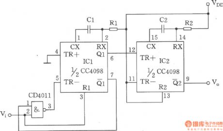
The chart shows a keyer oscillator composed of double monostable triggerCC4098, four 2 input NAND Gate CC4011. The circuit is a keyer oscillator with adjustable keying frequency and duty cycleformed by the monostable trigger, it ismainly usedfor the low frequency signal generatorrequiring less precision.
(View)
View full Circuit Diagram | Comments | Reading(12)
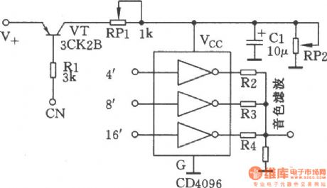
Multi-output crystal oscillator
Published:2011/4/19 1:44:00 Author:Ecco | Keyword: Multi-output , crystal, oscillator
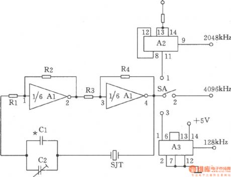
The chart shows the multi-output crystal oscillator. It is mainly composed of three gates of A1, four resistors, two capacitors and a crystal. Rl ~ R4 bias two inverters in the linear range, and they are connected between the pin 4 and pin1 of A1 by the crystal SJT, and they are used to provide feedback loop. It only produces frequency on the fundamental frequency of crystal. The selection of components: capacitor Cl is 15p (vernier capacitor). Resistors Rl, R3 are 220Ω, R2 is 560Ω, R4 is 1.8kΩ, R5 is 1kΩ, the nominal power is l/8W. IC Al is 7404, A2 is the 74LS74, A3 is the 74LS393. Crystal SJT is SW60A-4096kHz. Switch SA is KNX (1 × 3).
(View)
View full Circuit Diagram | Comments | Reading(704)
Square wave and sine wave generator
Published:2011/4/19 1:33:00 Author:Ecco | Keyword: Square wave, sine wave, generator
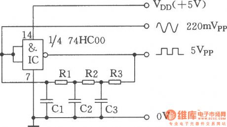
The chart shows the square wave and sine wave generator. It is a clock generator composed of an ordinary inverting gate and a few components, and it can output two waveforms with the same frequency simultaneously: square wave and sine wave. The oscillator can work well in the frequency of 100Hz ~ 10MHz. If using non-buffered output stage 74HCU00 replaces the 74HC00, it will have a better effect. (View)
View full Circuit Diagram | Comments | Reading(2245)
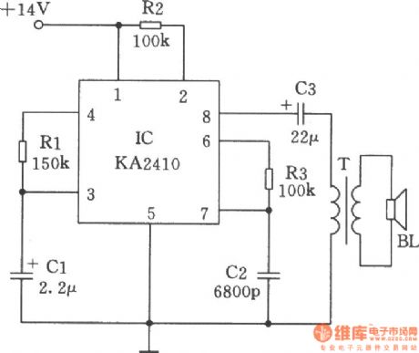
Analog sound generator made by telephone ringing IC
Published:2011/4/19 1:06:00 Author:Ecco | Keyword: Analog, sound generator , telephone ringing , IC
View full Circuit Diagram | Comments | Reading(686)
Adjustable duty cycle multivibrator composed of 555
Published:2011/4/19 1:08:00 Author:Ecco | Keyword: Adjustable, duty cycle , 555, multivibrator
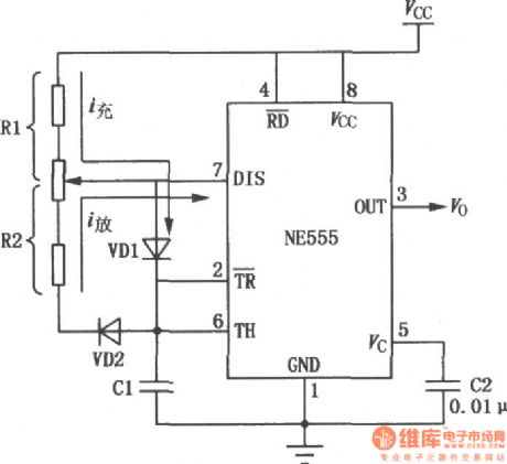
View full Circuit Diagram | Comments | Reading(1055)
The high voltage electrostatic generator circuit diagram composed of NE555
Published:2011/4/19 1:00:00 Author:Ecco | Keyword: high voltage, electrostatic , generator

The multi-function high-voltage electrostatic generator is based on 555, if matching with high back voltage diode and discharge brush pin, it can be used as a negative oxygen ion generator, ignition, static vacuum cleaner, or high security, etc. 555 and R1, R2, C2 form a multivibrator with non-steady state, the oscillation frequency F = 1.44 / (R1 +2 R2) C2, the argument in the figure is about 20KHZ. After boosted by the transformer T1,then it will get 20KHZ 10KV high voltage on secondary of T1, and it will be 7KV after rectified by D1, the load current can reach 50UA. (View)
View full Circuit Diagram | Comments | Reading(7633)
Linear CMOS oscillator
Published:2011/4/18 22:26:00 Author:Ecco | Keyword: Linear, CMOS , oscillator
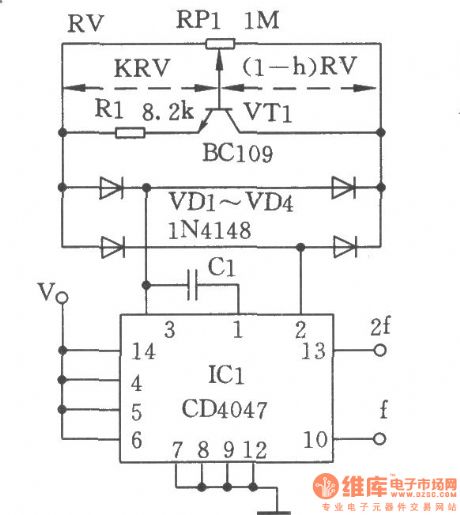
The linear CMOS oscillator circuit is shown as the chart. Just using a potentiometer RPl to make the CD4047 CMOS oscillator frequency be adjusted in the range of 1:100, and then accessing a transistor used as a variable resistor, and that is a regulator circuit with a line relationship to frequency. The emitter resistor R1 of VTl and base voltage could set the collector current. The bridge composed of diode VDl ~ VD4 ensures the symmetry work in positive and negative half-cycle.
(View)
View full Circuit Diagram | Comments | Reading(1168)
Triangle wave and square wave generator composed of NE555
Published:2011/4/18 22:16:00 Author:Ecco | Keyword: Triangle wave , square wave , generator
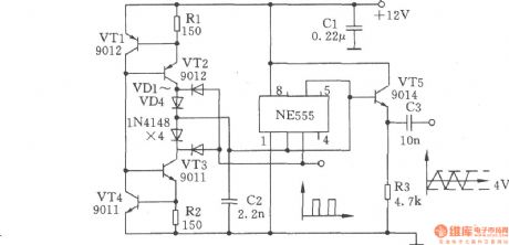
Triangle wave and square wave generator composed of NE555 is shown in the chart. VTl, VT2 and resistor Rl constitute a constant current source,which is used to make the linear charge for the capacitor C2; VT3, VT4 and resistor R2 constitute a constant current source, which is used to make the linear discharge for the capacitor C2.
(View)
View full Circuit Diagram | Comments | Reading(3530)
The function generator composed of 555 timer
Published:2011/4/18 21:04:00 Author:Ecco | Keyword: function generator , 555 , timer

The chart shows a function generator circuit composed of 555 timer. The circuit consists of a CH7555 timer and some transistors and RC components. It can generate triangle wave, square wave, sine wave, sawtooth and square wave sweep simultaneously. Ramp can be positive or negative. The frequency of various waveforms is adjustable from 0.1Hz ~ 100kHz, the amplitude of square wave is 5 ~ 15V, it can directly drive TTL circuits (power supply is 5V). Nonlinear ramp is below 1%, sine wave distortion is less than 3%.
(View)
View full Circuit Diagram | Comments | Reading(6005)
Switching alarm sound generator(KD9561)
Published:2011/4/18 21:37:00 Author:Ecco | Keyword: Switching , alarm sound , generator
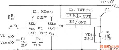
KD9561 is a CMOS four syllables music IC. With an oscilloscope observing the output waveform frequency square wave signal, the logic circuit can be considered as a digital signal. TWH8778 is the high power switching IC, it is suitable for processing digital signals, and it can be connected to CMOS IC directly as its high input impedance. The maximum output frequency of KD9561 is several thousand Hz, and TWH8778 can work up to 15 kHz. So there is not a matter of time digital signal processing when the former controlling the latter,and it should combine both and form a switching amplifying alarm sound generator. It can be used as police cars, ambulances, fire trucks and other alarm generator. Comparing with other linear audio amplifier, it has the advantages of simple structure, high efficiency, excellent cost. Although the sound quality is not perfect, its output power of amplifier could satisfy the requirements of general alarm sound, and the alarm generator does not need high-fidelity. The circuit is as shown in the chart.
(View)
View full Circuit Diagram | Comments | Reading(2056)
Pulse signal source with independently adjustable frequency and pulse(CD4011)
Published:2011/4/18 21:10:00 Author:Ecco | Keyword: Pulse signal source , independently , adjustable, frequency , pulse


When general pulse generator adjust its oscillation frequency, the signal pulse width is also changed. Conversely, when it needs to change the pulse width, the oscillation frequency is changed. The circuit can make the pulse width and frequency be adjusted separately, they are independent from each other. The circuit shows in Fig.
(View)
View full Circuit Diagram | Comments | Reading(1266)
Digital electronic organ envelope generator
Published:2011/4/18 21:16:00 Author:Ecco | Keyword: Digital, electronic organ , envelope generator
View full Circuit Diagram | Comments | Reading(675)
5Hz ~ 5MHz function generator composed of MAX038
Published:2011/4/18 20:17:00 Author:Ecco | Keyword: 5Hz ~ 5MHz , function generator

The 5Hz ~ 5MHz function generator circuit is shown in the chart. The circuit is a 5Hz ~ 5MHz function generator circuit, which could output the square wave, sine wave and triangular wave according to the need. The integrated circuit MAX038 is a special function generator which sets the oscillation frequency by the current of the input current terminal IIN. It changes the reference voltage into current by a resistor, the current flowing the end of FADJ is used to adjust the frequency. The frequency range of the circuit is set as multiples of 10. The timing capacitor is changed in the range of 75pF ~ 10μF. As the wire connection has an effect on working capacitor when the frequency is 5MHz, it could increase a CTc variable condenser in 50pF connecting to 75pF working capacitor in parallel, and it is easy to correct the high frequency. Frequency setting potentiometer PR1 adopts a resistor with 10 laps. The circuit is characterized by simple structure, adjustable components, reliable working.
(View)
View full Circuit Diagram | Comments | Reading(9134)
The function generator using 8038
Published:2011/4/18 20:16:00 Author:Ecco | Keyword: function generator
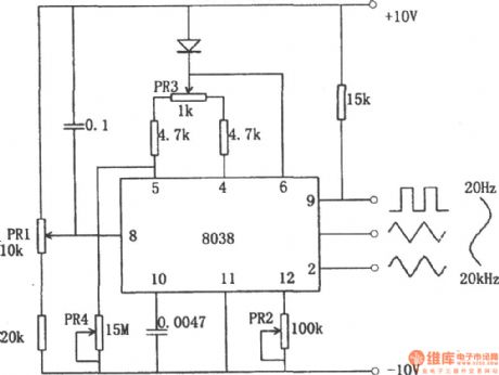
The function generator using 8038 is shown in the chart. The function generator using integrated circuit chip 8038 can get square, triangle wave and sine wave simultaneously. Triangular wave is directly formed by discharging from the constant capacitor; square wave received by the controlling signal; sine wave received by the triangular wave passing the approximation circuit. The sine curve obtained like this is not a smooth sine curve, and the distortion is about 1% and it can meet the needs of general purpose. The potentiometer PR1 in the circuit is used to adjust the frequency, its range is in 20Hz to 20kHz. PR2 is used to adjust the waveform distortion, PR3 is used to adjust the duty cycle of the waveform.
(View)
View full Circuit Diagram | Comments | Reading(6956)
Multi-functional sound generator composed of NE555、CC4051
Published:2011/4/18 20:13:00 Author:Ecco | Keyword: Multi-functional sound generator

This circuit is mainly used for regular alarm and audio generator in electronic toys. The circuit is characterized by a large range of supply voltage changing adaptation, it can work under 4 ~ 18V. Tone and tempo do not change by the altering of supply voltage, it can be used to indicate various states.
(View)
View full Circuit Diagram | Comments | Reading(1575)
| Pages:189/195 At 20181182183184185186187188189190191192193194195 |
Circuit Categories
power supply circuit
Amplifier Circuit
Basic Circuit
LED and Light Circuit
Sensor Circuit
Signal Processing
Electrical Equipment Circuit
Control Circuit
Remote Control Circuit
A/D-D/A Converter Circuit
Audio Circuit
Measuring and Test Circuit
Communication Circuit
Computer-Related Circuit
555 Circuit
Automotive Circuit
Repairing Circuit