
Signal Processing
Index 187
4kHz harmonic generator
Published:2011/4/21 5:06:00 Author:Ecco | Keyword: 4kHz , harmonic , generator

Harmonic generator is the differential type, which consists of a symmetrical differential amplifier circuit to impulse the difference in half-cycle rectangularly, and it is coupled push-pull by output transformer, the harmonic circuit is simple, convenience for measurement, low-cost, and it retains its symmetric pulse characteristics, its performance is similar with magnetic saturation type. The chart shows 4kHz harmonic generator circuit. Its frequency is controlled by the master oscillator, odd and even harmonics can be used as carrier and pilot of presetting, accessing, group roads modulation and demodulation for communication machine.
(View)
View full Circuit Diagram | Comments | Reading(836)
Against electric shock language warning circuit diagram
Published:2011/4/24 20:50:00 Author:Rebekka | Keyword: Against electric shock, language warning
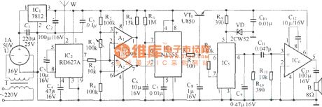

This circuit can be used to warn against electric shock for transformation and distribution facilities, when someone enters the detection range of the microwave device, the circuit will be issued the sound of on electricity, do not close . Here is the circuit.
IC5 is software package language integrated circuit. Here are the shape and connection diagram.
(View)
View full Circuit Diagram | Comments | Reading(1147)
Low frequency signal generator with high performance and composed of F007
Published:2011/4/21 6:00:00 Author:Ecco | Keyword: Low frequency, signal generator , high performance

The chart shows the low frequency signal generator circuit with high performance. The circuit is characterized by a steady increase performance, high output power, low waveform distortion. It is an ideal source of low frequency measurement signal. In the figure, the op amp A and its feedback network form a typical Wien oscillator, the oscillation frequency: f0 = 1/2. The output of RCA2 connecting to the OCL complementary push-pull amplifier may improve the circuit's load capacity. Operational amplifier A1 connected as the negative half-wave amplifier, and it forms a steady negative feedback circuit by combining with W1, R4, C1, T1 and other components. Potentiometer W1 adjusts the output rate, and it is used as sampler in the feedback loop. In order to ensure small waveform distortion, generally it should make R1C1 ≥ 20πRC. The circuit output amplitude is 0.5 ~ 5V, output current is 0 ~ 1A, the frequency adjustment range is 10Hz ~ 10kHz, the output resistance is less than or equal to 0.05Ω, harmonic distortion is less than 0.1%.
(View)
View full Circuit Diagram | Comments | Reading(3137)
The low frequency various waveforms generator(741)
Published:2011/4/22 2:58:00 Author:Ecco | Keyword: low frequency, various waveforms , generator
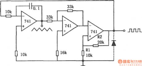
The chart shows a low frequency various waveforms generator circuit. The circuit can output two waveforms, the triangular wave and square wave. In the circuit, the first level is a standard integrator; second level is the inverter with gain in 1; the third level is a comparator with hysteresis. In the third stage without the diode, the circuit output is positive, the integrator output is negative syncline wave, which will be positive by reverse-phase helical wave and added to the comparator. When the ramp rate reaches the comparator threshold level Vo = R1 / (R1 + R2), the output is negative, then the integrator output is positive ramp; when its amplitude reaches the threshold level, the circuit has changed state, therefore, the first stage outputs triangle wave, the third stage outputs square wave, the phase difference between them is 180o. If adding a diode to the third level output, as the diode clamping action, the negative output of the comparator is -0.7V, then the circuit outputs sawtooth and pulse waves. Whether additional diodes, the output frequency is determined by the integrator time constant, power supply voltage and the partial pressure ratio of the comparator, its limit depends on the op amp's slew rate. The circuit limiting frequency is 5kHz. (View)
View full Circuit Diagram | Comments | Reading(1284)
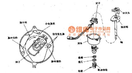
Beijing Cherokee light off-road vehicles sync signal sensor structure circuit diagram
Published:2011/4/25 1:22:00 Author:Rebekka | Keyword: Beijing Cherokee, light off-road vehicles, sync signal sensor
View full Circuit Diagram | Comments | Reading(458)
Flashing trigger circuit
Published:2011/4/25 2:39:00 Author:Nicole | Keyword: flashing, trigger
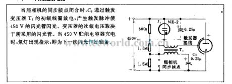
When the synchronous contact of camera is closed, C2 discharges by triggering the primary coil of transformer T1, it will produce a trigger pulse to make 450V flashtube flash. The secondary voltage of transformer is determined by the adopted flashtube. When 450V energy storage capacitor is charging, neon light will indicate to get ready for the next flashing. (View)
View full Circuit Diagram | Comments | Reading(372)
High and low frequency signal generator
Published:2011/4/21 6:31:00 Author:Ecco | Keyword: High frequency, signal generator, low frequency

The high and low frequency signal generator shown as the chart can produce low frequency signal with 1kHz, IF signal with 465kHz and high frequency signal with 525 ~ 1605kHz, it can help debug on the radio or other circuit, and it is suitable for beginners. Transistor VTl ~ VT3: selecting 3DGl00, 3DG201 other high-frequency low-power silicon tube, fT> 100MHz, β value is between 50 to 100. C7 uses 7/270pF radio with double or a single connecting capacitor. Oscillation transformer T is restructured on the radio, the core uses a 0.08mm high strength wire with 100 turns and rolled on L1, 35 turns on L2. C8 uses 510pF mica capacitor. Q uses three-stage type of 465kHz IF ceramic filter. Sl uses DPDT switch type. Other values are shown in Figure
(View)
View full Circuit Diagram | Comments | Reading(1255)
Simple high-frequency signal generator
Published:2011/4/20 6:51:00 Author:Ecco | Keyword: Simple , high-frequency , signal generator
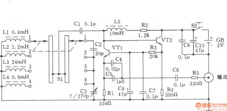
The chart shows a simple high-frequency signal generator. Changing the inductance of LC resonant circuit by the band switch Sl will change the frequency range of high frequency oscillation. This machine can be divided into four stages: the first stage is in 0.4 ~ 2MHz; the second stage is in 2 ~ 10MHz; the third stage is in 9 ~ 45MNz; fourth stage is in 60 ~ 110MHz. Components Selection: VTl, VT2 use the NPN silicon tube with fT ≥ 800MHz, β ≥ 100 of, such as 9018, C535 and so on. All resistors use 1/8W carbon film resistors. Capacitor C5 uses a monolithic capacitor or other ceramic capacitor. L2, L3, L4, L5 use high-frequency magnetic inductors and they can also be self-wound. Ll uses Φ0.6mm high strength wire with 8 flat close turns, and it is wound as the coil with inner diameter in Φ7mm . Sl uses the two-pole four roll band switch.
(View)
View full Circuit Diagram | Comments | Reading(2140)
Three waveform signal generator
Published:2011/4/22 1:40:00 Author:Ecco | Keyword: Three waveform, signal generator

TCL8038 is a dedicated function generator circuit with a variety of waveform output function (square wave, triangle wave, sine wave). The operating current is about l0mA with positive and negative power. the circuit is shown as the chart. C5 ~ C8 use the capacitors with small temperature coefficient and the capacitance error. Sl can output 1Hz pulse when the block being C8. RP2 uses 51 ~ 100kΩ double connection potentiometer to facilitate the frequency scale. RPl, RP3 are used to fine-tune the output waveform and make the upper and lower peaks along the smooth. Sl is the frequency of coarse block, RP2 is fine-tune frequency potentiometer. When debugging, the frequency scale calibration could be made with the aid of a digital frequency meter. And the waveform is measured by oscilloscope, adjusted by the potentiometer RPl and RP3. RPl makes the duty cycle of square wave modulation be 50% , adjusting RP3 could make the sine wave signal tend to be more smooth. The frequency of the signal generator is decided by the formula 0.3/RAv · (C5 ~ C8) and its frequency range is 1Hz ~ 1MHz. (View)
View full Circuit Diagram | Comments | Reading(879)
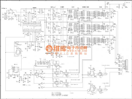
TV signal turning VGA signal circuit diagram
Published:2011/4/25 1:36:00 Author:Ecco | Keyword: TV signal , turning , VGA signal
View full Circuit Diagram | Comments | Reading(1549)
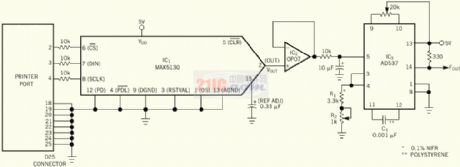
Programmable frequency generator circuit made by printer port
Published:2011/4/25 1:24:00 Author:Ecco | Keyword: Programmable , frequency generator , printer , port
View full Circuit Diagram | Comments | Reading(578)
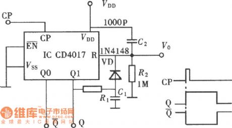
Mono-stable Trigger Circuit Composed of CD4017
Published:2011/4/24 21:17:00 Author:Sue | Keyword: Mono-stable, Trigger
View full Circuit Diagram | Comments | Reading(572)
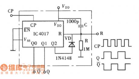
Bistable Trigger Circuit Composed of CD4017
Published:2011/4/24 21:20:00 Author:Sue | Keyword: Bistable, Trigger
View full Circuit Diagram | Comments | Reading(604)
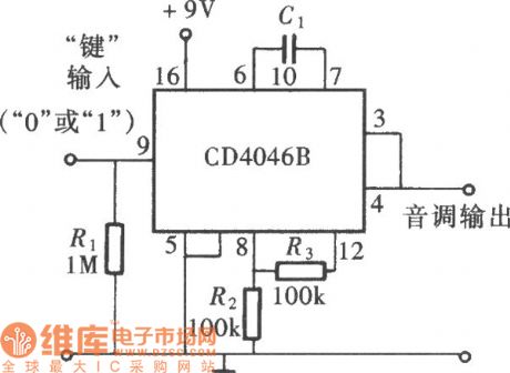
Frequency Signal Trace Circuit(PLL) Composed of CD4046
Published:2011/4/24 21:02:00 Author:Sue | Keyword: Frequency Signal, Trace, (PLL)
View full Circuit Diagram | Comments | Reading(560)
Multi-purpose Signal Generator Circuit
Published:2011/4/24 19:55:00 Author:Christina | Keyword: Multi-purpose, Signal Generator

The Multi-purpose Signal Generator Circuit is as shown:
(View)
View full Circuit Diagram | Comments | Reading(539)
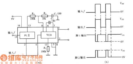
Square Wave Signal Generator Circuit Composed of CD4046
Published:2011/4/22 22:48:00 Author:Sue | Keyword: Square Wave, Signal, Generator
View full Circuit Diagram | Comments | Reading(814)
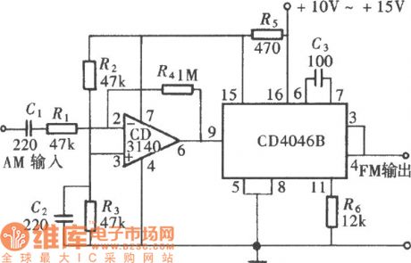
FM Signal Generator Circuit Composed of CD4046
Published:2011/4/22 22:51:00 Author:Sue | Keyword: FM, Signal, Generator
View full Circuit Diagram | Comments | Reading(1487)
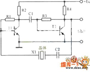
ZXB-2 Type Quartz Crystal Oscillator Circuit
Published:2011/4/23 8:56:00 Author:Robert | Keyword: Quartz Crystal Oscillator
View full Circuit Diagram | Comments | Reading(539)
Multi-Function Infrared Control Counter Circuit
Published:2011/4/24 6:35:00 Author:Robert | Keyword: Multi-Function, Infrared, Counter
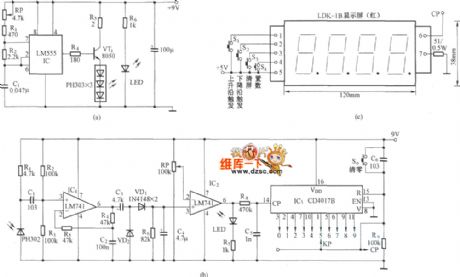
Multi-Function Infrared Control Counter Circuit is shown below:
(View)
View full Circuit Diagram | Comments | Reading(996)
0.001Hz Sine Wave Oscillator Circuit
Published:2011/4/21 20:25:00 Author:Robert | Keyword: 0.001Hz, Sine Wave, Oscillator
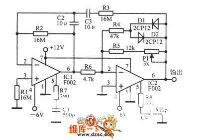
0.001Hz sine wave oscillator circuit is shown below:
(View)
View full Circuit Diagram | Comments | Reading(794)
| Pages:187/195 At 20181182183184185186187188189190191192193194195 |
Circuit Categories
power supply circuit
Amplifier Circuit
Basic Circuit
LED and Light Circuit
Sensor Circuit
Signal Processing
Electrical Equipment Circuit
Control Circuit
Remote Control Circuit
A/D-D/A Converter Circuit
Audio Circuit
Measuring and Test Circuit
Communication Circuit
Computer-Related Circuit
555 Circuit
Automotive Circuit
Repairing Circuit