Signal Processing
The low frequency various waveforms generator(741)
Published:2011/4/22 2:58:00 Author:Ecco | Keyword: low frequency, various waveforms , generator | From:SeekIC

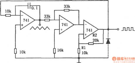
The chart shows a low frequency various waveforms generator circuit. The circuit can output two waveforms, the triangular wave and square wave. In the circuit, the first level is a standard integrator; second level is the inverter with gain in 1; the third level is a comparator with hysteresis. In the third stage without the diode, the circuit output is positive, the integrator output is negative syncline wave, which will be positive by reverse-phase helical wave and added to the comparator. When the ramp rate reaches the comparator threshold level Vo = R1 / (R1 + R2), the output is negative, then the integrator output is positive ramp; when its amplitude reaches the threshold level, the circuit has changed state, therefore, the first stage outputs triangle wave, the third stage outputs square wave, the phase difference between them is 180o. If adding a diode to the third level output, as the diode clamping action, the negative output of the comparator is -0.7V, then the circuit outputs sawtooth and pulse waves. Whether additional diodes, the output frequency is determined by the integrator time constant, power supply voltage and the partial pressure ratio of the comparator, its limit depends on the op amp's slew rate. The circuit limiting frequency is 5kHz.
Reprinted Url Of This Article:
http://www.seekic.com/circuit_diagram/Signal_Processing/The_low_frequency_various_waveforms_generator741.html
Print this Page | Comments | Reading(3)

Article Categories
power supply circuit
Amplifier Circuit
Basic Circuit
LED and Light Circuit
Sensor Circuit
Signal Processing
Electrical Equipment Circuit
Control Circuit
Remote Control Circuit
A/D-D/A Converter Circuit
Audio Circuit
Measuring and Test Circuit
Communication Circuit
Computer-Related Circuit
555 Circuit
Automotive Circuit
Repairing Circuit
Code: