High Frequency Signal Generating
Simple high-frequency signal generator
Published:2011/4/20 6:51:00 Author:Ecco | Keyword: Simple , high-frequency , signal generator | From:SeekIC

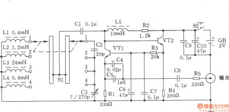
The chart shows a simple high-frequency signal generator. Changing the inductance of LC resonant circuit by the band switch Sl will change the frequency range of high frequency oscillation. This machine can be divided into four stages: the first stage is in 0.4 ~ 2MHz; the second stage is in 2 ~ 10MHz; the third stage is in 9 ~ 45MNz; fourth stage is in 60 ~ 110MHz. Components Selection: VTl, VT2 use the NPN silicon tube with fT ≥ 800MHz, β ≥ 100 of, such as 9018, C535 and so on. All resistors use 1/8W carbon film resistors. Capacitor C5 uses a monolithic capacitor or other ceramic capacitor. L2, L3, L4, L5 use high-frequency magnetic inductors and they can also be self-wound. Ll uses Φ0.6mm high strength wire with 8 flat close turns, and it is wound as the coil with inner diameter in Φ7mm . Sl uses the two-pole four roll band switch.
Reprinted Url Of This Article:
http://www.seekic.com/circuit_diagram/Signal_Processing/High_Frequency_Signal_Generating/Simple_high_frequency_signal_generator.html
Print this Page | Comments | Reading(3)

Article Categories
power supply circuit
Amplifier Circuit
Basic Circuit
LED and Light Circuit
Sensor Circuit
Signal Processing
Electrical Equipment Circuit
Control Circuit
Remote Control Circuit
A/D-D/A Converter Circuit
Audio Circuit
Measuring and Test Circuit
Communication Circuit
Computer-Related Circuit
555 Circuit
Automotive Circuit
Repairing Circuit
Code: