
Signal Processing
Index 184
Car audio btl amplifier IC figure
Published:2011/5/1 22:44:00 Author:Christina | Keyword: Car audio, btl amplifier IC

This article introduces the amplifier section of the car's sound system by my measurement and information collection.
1.brand device's specific IC
Figure 1 is the pal006a which is produced by the Pioneer company (Measurement model deh-p3300), this ic uses the mosfet output class and is in the 25-pin unilateral double-row zigzag package, it has 4 btl amplifiers with the maximum power of 50Wx4. Figure 2 is the Ford xllf-18c870-ed's amplifier class which is produced by the Alpine company. This ic is the philips 70039ab model, and is 17-pin unilateral dual in-line package, it has two groups of btl circuit. This ic is also used in Clarion Corporation's radio.
2.ta8210ah ~ ta8215l series of btl stereo ic that can be used in wide range of applications
Figure 3. The ta8210ah is in 17-pin unilateral dual in-line package, ta82l5l is in 17-pin single in-line package.
3.Mono btl specific ic
4.Other btl specific ic
(View)
View full Circuit Diagram | Comments | Reading(6529)
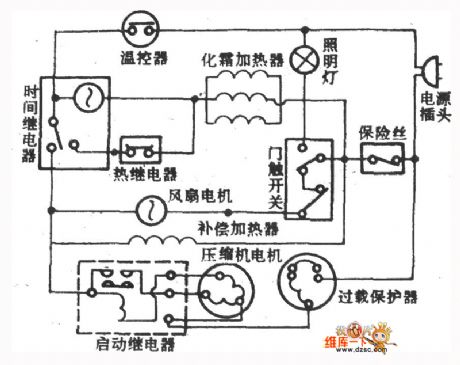
Taiwan timing electric heating defrost fridge
Published:2011/5/2 18:38:00 Author:Christina | Keyword: Taiwan, timing, electric heating, defrost

The Taiwan timing electric heating defrost fridge is as shown:
(View)
View full Circuit Diagram | Comments | Reading(449)
Taiwan hot gas defrost fridge (jet) interval-cool fridge circuit
Published:2011/5/2 8:52:00 Author:Christina | Keyword: Taiwan, hot gas, defrost, jet, interval-cool

The Taiwan hot gas defrost fridge (jet) interval-cool fridge circuit is as shown:
(View)
View full Circuit Diagram | Comments | Reading(1383)
The California SR-190 cool refrigerator circuit
Published:2011/5/2 5:05:00 Author:Christina | Keyword: California, cool refrigerator
The California SR-190 cool refrigerator circuit is as shown:
(View)
View full Circuit Diagram | Comments | Reading(399)
RP Addition Circuit
Published:2011/5/2 2:53:00 Author:Felicity | Keyword: RP Addition Circuit,

RP Addition Circuit is that several input signals are inputed at the inverting input of integrated operational amplifier. And the output signal is the sumof reversing enlarging proportion. (View)
View full Circuit Diagram | Comments | Reading(453)
Active load and the ringing signal detection circuit diagram
Published:2011/4/29 2:24:00 Author:Rebekka | Keyword: Active load , the ringing signal detection
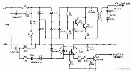
The circuit is simple, reliable and versatility. It is suitable for HJD05 switche. (View)
View full Circuit Diagram | Comments | Reading(593)
High-end telephone equipment circuit diagram
Published:2011/4/29 3:18:00 Author:Rebekka | Keyword: High-end telephone equipment
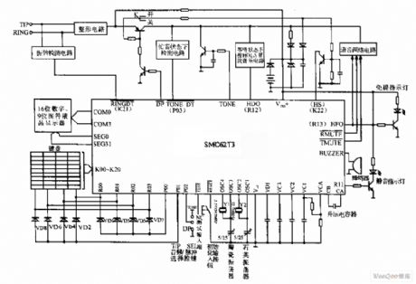
High-end telephone equipment circuit diagram. (View)
View full Circuit Diagram | Comments | Reading(1217)
Transmission attenuation test circuit diagram
Published:2011/4/29 2:58:00 Author:Rebekka | Keyword: Transmission attenuation test

Transmission attenuation test circuit is shown as above. The test circuit is composed of the test signal generator E, the equivalent load resistor attenuator ATT, the corresponding indicator LM DPDT switch and other accessories. Use the method of comparison, the attenuation value of the circuit under test calls can be measured. (View)
View full Circuit Diagram | Comments | Reading(478)
Low drift amplification circuit composed of TL592B
Published:2011/4/29 2:40:00 Author:TaoXi | Keyword: Low drift, amplification circuit

The Low drift amplification circuit composed of TL592B is as shown. (View)
View full Circuit Diagram | Comments | Reading(755)
Audio preamp circuit composed of DY336
Published:2011/4/29 2:22:00 Author:TaoXi | Keyword: Audio, preamp circuit

The audio preamp circuit supports the functions of signal switching, volume adjustment and buffer.etc, and you can add the 10 times voltage to amplify it to make the better sound quality.
One amplifier channel of the pre-amplifier is as shown. The circuit uses three DY336 low noise, high quality op amps. A1 is the input signal's buffer follower, it can reduces the burden of the signal source. The negative feedback volume controller is composed of the A2 and RPl, this kind of volume adjustment method can reduces the distortion and noise. Compare with the conventional volume control method, the transient distortion is smaller because of the no RC constant's integration effect. The output stage is composed of the A3, VTl and VT2, this stage works under the single-end A condition, the Single-end output contains even harmonics to make the sound quality better, and the current driving force of transistor is stronger, the low level control will be better.
(View)
View full Circuit Diagram | Comments | Reading(914)
Walkman bass upgrade circuit
Published:2011/4/29 1:22:00 Author:TaoXi | Keyword: Walkman, bass upgrade

The LAG665 and LAG668 are single cassette player IC, LAG668 is the improved mode of LAG665, their internal circuits are very similar. For the bass lovers, they can replace LAG665 with LAG668 and change the external circuits to upgrade the bass. Low frequency enhance measures is always to attenuate high or medium frequency. After the high or medium frequency has been attenuated, the signal falls off to influence audio sensitivity and dynamic effects, so the volume falls down and can not meet rated output power. The remedial measures are: 1.Improve the voltage gain of the front stage; 2. Increase the level of first voltage amplification; 3. Improve the rear level's input impedance to improve the input sensitivity by small stimulation; 4. Increase the gain of amplifier. The LAG668 uses the 3 and 4, the first: improve the rear stage's (attenuator) input impedance to 200kt2; the second: improve the power amplifier's voltage gain to 38dB. The Walkman bass upgrade circuit is as shown, channel 1's tone network is the same to channel's. (View)
View full Circuit Diagram | Comments | Reading(3376)
Double frequency sound and light source circuit diagram composed of SGZ07
Published:2011/4/28 23:01:00 Author:Ecco | Keyword: Double frequency , sound , light , source , alarm IC

Double frequency sound and light source circuit diagram composed of SGZ07 sound and light alarm IC.
The corresponding relationship between C1, C2 and the output signal.
(View)
View full Circuit Diagram | Comments | Reading(629)
The logic pulse generator composing of CD4011
Published:2011/4/18 20:16:00 Author:Ecco | Keyword: logic pulse generator

Logic pulse generator can transport either positive or negtive logic pulse according to the need, the circuit is as shown. The circuit consists of a four - two input NAND gate CD4011, of which the door Dl, D2 form a RS trigger pulse, D3, D4 are used as inverters. It isolates the output of D1 and then drives a light-emitting diode after reversing, it is used to indicate the logic state of the output pulse.
(View)
View full Circuit Diagram | Comments | Reading(2541)
Stereo headphone frequency response tester circuit
Published:2011/4/29 0:49:00 Author:TaoXi | Keyword: Stereo headphone, frequency response tester

The stereo headphone frequency response tester circuit is as shown in the figure, IC1 is the general-purpose four op amp LM324, the Wien bridge sine wave generator is composed of the IC1-1 and IC1-2; amplifier IC1-3, IC1-4 are the voltage follower. The positive feedback circuit of Wien bridge sine wave generator is composed of the C2、R2 and C1, (R1+RP1), the negative feedback circuit is composed of the R3and R5. One of the greatest feature of this circuit is that the general Wien bridge sine wave oscillator (R1+RPl) is usually grounded, but this (R1+RPl) connects to the IC1-2 invert input port's virtual location. The stable-width circuit is composed of the VDl, VD2 and RP2, in the oscillation process, VDl, VD2 alternately turns on, when the amplitude increases, the negative feedback increases too. And it limits the amplitude continues to increase; and vice versa. Adjust the RPI can make the oscillation frequency between 100Hz~125kHz. (View)
View full Circuit Diagram | Comments | Reading(1960)
Variable pulse width pulse generator circuit
Published:2011/3/23 20:35:00 Author:may | Keyword: pulse generator

Pulse frequency depends on the size of the capacitance C, according to need can use 0.1uF or other value. 12KΩ resistance is load resistor required by operational amplifier open collector.
(View)
View full Circuit Diagram | Comments | Reading(1477)
Sine oscillating circuit diagram
Published:2011/3/23 20:03:00 Author:may | Keyword: Sine oscillating

The diagram is circuit which consists of VD1, VD2 two variable capacitance diodes, its oscillation frequency is concerned with R1、VD1-R2、VD2, in order to adjust frequency range, the capacitances and resistances of two Bridge road branchs must change the same value of number at the same time. So need to use coaxial connecting two potentiometer or duplex capacitors.
(View)
View full Circuit Diagram | Comments | Reading(520)
Single frequency sound and light source circuit diagram composed of SGZ07 sound and light alarm IC
Published:2011/4/28 20:33:00 Author:Ecco | Keyword: Single frequency , sound , light, source , alarm IC


Single frequency sound and light source circuit diagram composed of SGZ07.
The characteristics between C1 and the output signal :
(View)
View full Circuit Diagram | Comments | Reading(716)
Automotive electronic equipment cooling fluid temperature gauge, oil pressure gauge circuit
Published:2011/4/28 19:12:00 Author:Christina | Keyword: Automotive electronic equipment, cooling fluid temperature gauge, oil pressure gauge
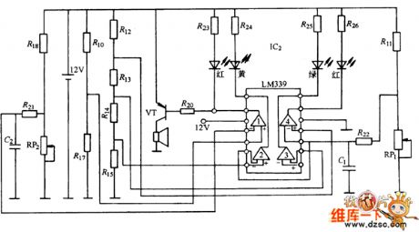
In order to understand and control the car engine's working-situation, and to detect and eliminate the failure, cars are equipped with the automotive electronic equipment cooling fluid temperature gauge, oil pressure gauge. As the figure 6-38 shown, the circuit can displays engine coolant temperature and oil pressure. It is composed of the coolant temperature sensor w1 (Thermistor type), the oil pressure sensor w2 (bimetallic resistance-type), the lm339 and the red, yellow, green light-emitting diode monitor. The coolant temperature sensor is in the engine water-jacket, the coolant temperature measurement circuit is composed of the coolant temperature sensor and resistance r11. The oil pressure sensor is in the engine's main oil pipeline, and the oil pressure measuring circuit is composed of the oil pressure sensor and resistance r18. The automotive electronic equipment cooling fluid temperature gauge, oil pressure gauge circuit is as shown:
(View)
View full Circuit Diagram | Comments | Reading(1279)
Fishing pulse circuit
Published:2011/4/28 18:57:00 Author:Christina | Keyword: Fishing, pulse
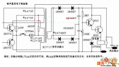
Debugging: Connect a 100W incandescent bulb to the output port of the circuit, then adjust the 100KK fine-tuning resistance to let the bulb sends out white light with light flash. (View)
View full Circuit Diagram | Comments | Reading(721)
lm1875 application experiment and current feedback btl circuit-design circuit
Published:2011/4/28 18:49:00 Author:Christina | Keyword: application experiment, current feedback btl, circuit-design

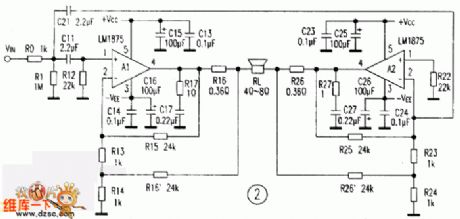
If the current becomes DC current and changes into the current feedback, the frequency response will become broad, and the bass power significantly enhanced, the ability of frequency resolution and alto texture will increase. If we compare this amplifier with the New Texas 6800 pure class A amplifier, use the Huiwei swan m1.2 speaker, in a 15 square meters room, this amplifier is very close to New Texas 6800 pure class A amplifier.
DC current negative feedback btl circuit is as shown in figure 2, abolishes the standard btl circuit's c12, c22, resistors r16 and r26 is the sample resistance, current feedback signal gets into the amplifier a1, a2 of the inverting input port through the r15、r16、r25、r26, and the resistances of r13、r14、r15、r16 determine the value of the amplifier gain.
Experiment with the circuit in Figure 2, anyway you turn off the power and input signal, DC output port has no DC current, and has no static output noise, the speaker just sends out the sound of pa when you opening it. So this experiment shows that this circuit is very stable, if you plug the input terminal when increasing the volume orin the static state, this circuit will not beself-excited. (View)
View full Circuit Diagram | Comments | Reading(3447)
| Pages:184/195 At 20181182183184185186187188189190191192193194195 |
Circuit Categories
power supply circuit
Amplifier Circuit
Basic Circuit
LED and Light Circuit
Sensor Circuit
Signal Processing
Electrical Equipment Circuit
Control Circuit
Remote Control Circuit
A/D-D/A Converter Circuit
Audio Circuit
Measuring and Test Circuit
Communication Circuit
Computer-Related Circuit
555 Circuit
Automotive Circuit
Repairing Circuit