
Signal Processing
Index 185
Three-step tone controller (STK3048) circuit
Published:2011/4/28 1:44:00 Author:TaoXi | Keyword: Three-step, tone controller

The three-step tone controller circuit is as shown. Core component STK3048 is the dual-channel low-noise voltage amplification thick block, it is one kind of cheap high voltage dual operational amplifier, particularly suitable for make the front- and tone circuits. This circuit is controlled by three-stage tone. By changing the proportion of each frequency in the music signal,we canimprove the system's audio features, so we get the good sound. (View)
View full Circuit Diagram | Comments | Reading(1042)
Electron coupled oscillator circuit
Published:2011/4/11 2:39:00 Author:may | Keyword: Electron coupled oscillator

This circuit connected directly with collector, thus good for heat dissipation, under a given device parameters, the working frequency is 30MHz , the output coupling high frequency is about 0.8W. The following diagram is electron coupled oscillator circuit.
(View)
View full Circuit Diagram | Comments | Reading(725)
5MHz clock signal generater circuit
Published:2011/4/24 1:10:00 Author:May | Keyword: clock signal generater

The transistor T1, T2 form a multiple harmonic oscillator, and connect to 500Ω adjustable resistance in series with fixed resistance R1 can adjust frequency. Transistor T3 and T4 compose output level, output current IQ is larger than 48mA when the low level UQL=0.4V, and 20mA when the high level UQH is 2.9V.
(View)
View full Circuit Diagram | Comments | Reading(450)
A8800 IF signal processing integrated circuit diagram
Published:2011/4/28 1:26:00 Author:Ecco | Keyword: IF, signal processing , integrated circuit
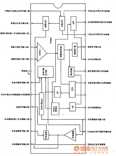
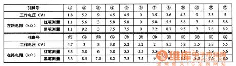
TA8800 is an IF signal processing integrated circuit produced by Toshiba, it is widely used in domestic and imported large screen color TV. 1. The features of functionTA8800 IC embedded video zoom, video detector, high frequency and IF AGC, VIF amplification, intermediate frequency amplification and sound processing circuit. 2. Pin functions and dataTA8800 integrated circuit block diagram and the pin functions are shown in Figure 1, the operating parameters are listed in Table 1. Figure 1 is the block diagram and pin functions of TA8800 integrated circuit. Table 1 shows operating parameters of TA8800 integrated circuit.
(View)
View full Circuit Diagram | Comments | Reading(470)
Wien bridge sine wave oscillator circuit composed of LM101A
Published:2011/4/20 6:19:00 Author:Ecco | Keyword: Wien bridge , sine wave , oscillator circuit

The chart shows the Wien bridge sine wave oscillator circuit. The amount of negative feedback circuit is determined by the internal resistance of FET. When the peak value of oscillator output reaches the regulated voltage of regulator diode D1, Q2 turns on, then the grid of Q1 FET becomes negative, Q1's drain - source resistance increases, the negative feedback increases, loop gain decreases. Similarly, when the oscillation amplitude decreases, the loop gain will increase, therefore, it can maintain a certain output range. C1, C2, R1 and R2 constitute a positive feedback loop to ensure the circuit oscillation. Connecting a l00kΩ resistor between drain and gate or gate and source of FET will ensure the FET working in the linear region and reducing distortion. Circuit oscillation frequency: f0 = 1/2π. According to the component value of the figure, the oscillation frequency R1C1 is calculated approximately 1.6kHz. (View)
View full Circuit Diagram | Comments | Reading(2020)
450/800Hz signal generator
Published:2011/4/20 7:01:00 Author:Ecco | Keyword: 450Hz , 800 Hz , signal generator

450/800Hz oscillator circuit shown as the chart is a transformer coupled oscillator. The changing of frequency is realized by changing the Tl tap of oscillation tank to achieve different inductance. Pulling the signal control switch S to the 1 block, the oscillation circuit C4 and l-2 end of Tl-side connects in parallel, the frequency is 800Hz, and it is output by VT2 emitter to the adjustable arm of RP potentiometer. Adjusting the potentiometer will change the size of 800Hz output. R4 in oscillation circuit is used to adjust the oscillation amplitude. Pulling the S to the 2 block, C and 1-3 phase of T1 connects, the oscillation frequency is 450Hz. Adjusting T1 threaded lever can fine-tune the oscillation frequency of the oscillator.
(View)
View full Circuit Diagram | Comments | Reading(455)
Quartz crystal sinusoidal oscillator
Published:2011/4/25 4:46:00 Author:Ecco | Keyword: Quartz crystal, sinusoidal oscillator

The circuit shown as the chart is a sine wave oscillator which is composed of the quartz crystal resonator SJT and one gate of six inverter IC CD4069. And comparing with ordinary RC phase shift oscillator, the crystal oscillator's frequency stability can be up to 0.00001 or higher. This is the high targets which RC phase-shift oscillator can not achieve (RC phase shift oscillator frequency stability can only reach the order of 0.01). CMOS NAND gate and negative feedback bias resistor Rl form the inverting amplifier. Quartz crystal SJT and Cl, C2 constitute a 7c positive feedback subcircuit. When quartz crystal is in the vicinity of its natural resonance frequency, it is self-inductive, the inductors and capacitors Cl, C2 constitute a resonant circuit, the forming selective frequency phase shift feedback network is back to the amplifier input to produce oscillation. Adjusting the capacitor C2 can fine-tune the oscillation frequency. Components Selection: Six inverter manifold A: CD4069. Capacitor Cl: 20pF, C2: 3 ~ 22pF, C3: 1000pF. Resistor Rl: 10MΩ. Crystal SJT: 32.768kHz. Circuit connection method: six integrated circuit CD4069 inverter only uses 1 / 6 door, the remaining doors can be used to connect to its input termination VDD or VSS when no other uses, the output is floating. (View)
View full Circuit Diagram | Comments | Reading(1196)
Stable sine wave oscillator composed of F007
Published:2011/4/21 6:39:00 Author:Ecco | Keyword: Stable sine wave oscillator

The chart shows the stable sine wave oscillator circuit. In order to obtain a stable oscillation, it requires a loop gain with 1. If the gain is too large, the waveform will occur distortion; if the gain is too small, the circuit will stop vibration. This circuit uses two diodes to stabilize the oscillation. When the output voltage is too low, the diode cuts off, negative feedback is cut off, the loop gain to improve the output voltage increased. When the output reaches a certain value, the diode conduction, the loop gain is improved, output voltage increases. And when the output rate reaches a certain value. The potentiometer in the figure is used to adjust the output amplitude and distortion. The oscillation frequency of the circuit is decided by the resistor R and capacitor C: f0 = 1/2πRC.
(View)
View full Circuit Diagram | Comments | Reading(710)
56 ~ 512kHz high frequency oscillator
Published:2011/4/20 22:05:00 Author:Ecco | Keyword: 56 ~ 512kHz , high frequency , oscillator


The chart shows the 56 ~ 512kHz high frequency oscillator. It consists of high-frequency oscillator, the alarm circuit. 1. Specifications: (1) Frequency range: 56 ~ 512 kHz; (2) Output Level: +5.5 ± ldB; (3) Frequency Accuracy: less than ± 20Hz; (4) warning signal: when stopping vibration, the warning light turns on and the circuit emits alarm sound. (5) Operating temperature: 0 ~ +45 ℃ assurance indicators, -10 ~ 0 ℃, +45 ~ +50 ℃; reliable working components’ choice: Transistor VTl ~ VT4: 3DGl01C, β = 65 ~ 85, VT5 ~ VT6: 3DGl308 , β = 85 ~ 115. Crystal SJT: the model is 101 quartz crystal, crystal with t feet that is GZC7-F. The choices of capacitors Cl and C4 are according to the attached table.
(View)
View full Circuit Diagram | Comments | Reading(1445)
Voltage-regulator tube high-frequency signal generator
Published:2011/4/25 4:33:00 Author:Ecco | Keyword: Voltage-regulator tube , high-frequency , signal generator

Using the breakdown characteristics of zener regulator can get the high frequency signal which can be up to several hundred MHz, the circuit is shown as the chart. The signal removing from the output end V01 is a single frequency signal, which can be used to fine-tune the resonant frequency of tuned circuit. The signal removing from the output end V02 is the broad spectrum of high-frequency signal, which can enter the tune the system between the input resonant circuit and the oscillator tuning circuit in superheterodyne radio circuit. Generator frequency range is l00kHz ~ 27MHz, which is divided into five bands of 100kHz ~ 300kHz ~ l MHz ~ 3MHz ~ 9MHz ~ 27MHz. Signal generator's output voltage is 9mV. Ll ~ L5 coil is rounded with skeleton, with fine-tuning core. Ll ~ L3 are enameled with Φ0.1mm wires, L4, L5 are enameled with Φ0.2mm wires. The number of turns of Ll ~ L5 is 270 +270, 260, 80, 30 and 10. After assembly, it needs to be corrected by the standard calibration signal generator, and mark the frequency scale on the knob of the variable capacitor C3. Adjusting Potentiometer make the output frequency signal be strongest. Regulator used in the circuit is without special requirements, but the value of the supply voltage should be higher than the regulator to ensure the regulator operating in the inflection point on the curve.
(View)
View full Circuit Diagram | Comments | Reading(685)
High frequency producing lamplighter
Published:2011/4/21 5:50:00 Author:Ecco | Keyword: High frequency , producing , lamplighter

The chart shows the high frequency producing lamplighter circuit. It uses the 8V ~ 14V battery as energy source, and boosted by oscillation and then lights 6W ~ 12W fluorescent lamp. The transistor VT can use 3DD12A, D3D4D, 3DD5C, 3DDl5A and other low-frequency high-power transistor, it should be installed the 70mm × 40mm × 2mm of aluminum radiator when assembling; potentiometer RP should use a small wire wound type; frequency pulse transformer T can be self-made by ferrite magnetic tank with diameter in 22mm; coil L1 uses a high-strength magnet wire with 9 turns and diameter in lmm and rolled flatly on framework; feedback coil L2 uses a high-strength magnet wire with 8 turns and diameter in 0.3mm and rolled flatly on L1; coil L3 uses a 0.2mm enameled high-strength magnet wire with 900 turns and diameter in 0.2mm.
(View)
View full Circuit Diagram | Comments | Reading(780)
Intermediate frequency signal generator made by 3L465 ceramic filter
Published:2011/4/24 22:32:00 Author:Ecco | Keyword: Intermediate frequency , signal generator, ceramic filter

Figure shows the intermediate frequency signal generator made by 3L465 ceramic filter, the line is simple, easy to start up, the resulting IF signal is stable, it has a good repeatability and outputs audio signal. Working principle: VTl, VT2 and related components form a multivibrator with frequency in 400Hz, it is used to modulate IF signal, audio signal can be output from the A point. VT3, VT4 form an IF signal generator, DL has the selected frequency effect. RP can change the oscillation intensity adjustment. Leading a wire of a few centimeters in B point to output modulated IF signal. Multivibrator can work when getting power if welding is correct. The inspection part of the IF signal generator circuit is correct, it can use a medium-radio to close to the B point leading wire, adjusting the RP make the radio receive the signal, then the adjustment is end. When using, the radio wave band switch should be put at medium wave, the variable capacitor is adjusted to the the low-spin, and then point B closing to the AM ferrite antenna coil lead wire, and then one by one repeatedly adjusting the frequency transformer make the speaker's voice or added to voltage be the maximum.
(View)
View full Circuit Diagram | Comments | Reading(1190)
2100Hz signal generator
Published:2011/4/22 2:13:00 Author:Ecco | Keyword: 2100Hz, signal generator

When 2100Hz output level is lower than normal level 3.5dB, the both ends voltage of C7 is about 3.4V and couldn't reach the trigger value, so VT4 stopd, VT5 is conducted. Thus VD5 and VT6 close, relay K loses electricity and releases, contacts K1-2, K8-9 are off, K8-9 is closed. No 2100Hz signal outputs, light-emitting diode VD7 displays a red warning signal. Potentiometer could adjust the action level value of relay K RP2. Component selection: VTl, VT3, VT4, VT5: 3DG6C, β = 50 ~ 115, VT2, VT6: 3DGl28, β = 85 ~ 115. Double color LED VD7: BT a 605 (red, green and white). Relay K: PR401-1250Ω. Oscillation transformer Tl: L1-2 is Φ0.11mm high-strength wire with 37 turns, L3-4 is 0.11mm with 713 turns, L5-6 is 0.1lmm high-strength wire with 358 turns. It uses tank-type ferrite with model in MTT22. Output transformer T2: L1-2 is Φ0.11mm high-strength wire with 141 turns, L3-4 is Φ0.12mm with 43 turns, L5-6 is Φ0.12mm with 177 turns. It uses tank-type ferrite with model in MTT22. The resistor selects the 1/4W 1/8W metal film resistor.
(View)
View full Circuit Diagram | Comments | Reading(551)
Fushibao induction cooker circuit
Published:2011/4/27 21:45:00 Author:Christina | Keyword: Fushibao, induction cooker circuit

The Fushibao induction cooker circuit is as shown in the figure. (View)
View full Circuit Diagram | Comments | Reading(5911)
400Hz signal source circuit
Published:2011/4/27 21:16:00 Author:Christina | Keyword: 400Hz, signal source

The 400Hz signal source circuit is as shown:
(View)
View full Circuit Diagram | Comments | Reading(456)
Low frequency Wien bridge sine wave oscillator(MC1456、μA741)
Published:2011/4/22 1:49:00 Author:Ecco | Keyword: Low frequency, Wien bridge, sine wave oscillator

Figure shows the low frequency Wien bridge sine wave oscillator circuit. The circuit uses the exponential characteristics of the diode to stabilize 0.001Hz sine wave generator amplitude, so as not to cause a larger time constant, because the diodes can quickly change their equivalent dynamic resistance. This stability is similar to the limiter. The 47kΩ resistor connecting to the diode in series is used to reduce the limiting effect of the diode, and can prevent the circuit distortion. In general Wien bridge oscillator, because of the limited input impedance of op amp, the R in the parallel RC can not be too high, so the oscillation frequency can not be too low. There are two op amps in the cirucit, RC is connected between the inverting input and output ens of op amp A1 and can increase the operational amplifier input impedance, so you can use a R with large resistance. The connection couldn't use FET input operational amplifier. (View)
View full Circuit Diagram | Comments | Reading(1510)
Low power Wien bridge oscillator composed of MC1454
Published:2011/4/21 6:07:00 Author:Ecco | Keyword: Low power , Wien bridge , oscillator


The chart shows the low power Wien bridge oscillator circuit. The circuit is characterized by little distortion when driving low impedance load and large capacitive loads. Operational amplifier used in the circuit could drive 8 ~ 10Ω load, the 10Ω load can provide 2 ~ 4V peak output voltage and the frequency is from 1Hz to 100kHz, distortion is less than 0.5%. Automatic gain control is achieved by a lamp L as the resistance of the bulb changing with the output voltage. Resistor R3 forms a negative feedback loop to determine the output signal amplitude. Capacitors C1 and C2, resistors R1 and R2 constitute a positive feedback. If the value of resistor R1 and the input impedance of the amplifier is equal, R2 = R1 / 2, C1 = C2, then the oscillation frequency; f0 = 1/2π,R1C1C3 is the high-frequency compensation capacitor. The following table lists the relationship between frequency and capacitance C1 (C2) .
(View)
View full Circuit Diagram | Comments | Reading(1065)
1488kHz signal generator and divider
Published:2011/4/21 6:22:00 Author:Ecco | Keyword: 1488kHz, signal generator, divider
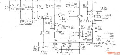
1488kHz master oscillator uses quartz crystal resonator stabilize frequency, the output is divided by the divider, then it gets three different square wave signal output in 4kHz, 12kHz, 124kHz. The circuit is shown as the chart. Transistors VTl, VT2, VT4, VT6: 3DG6C, β = 50 ~ 85, VT3: 3CG3D, β = 50 ~ 85, VT5: 3DGl308, β = 65 ~ 115. Variable devices T: using tank-shaped ferrite, model is MTT22F. Ll-2 uses Φ0.35mm high-strength wire with 36 turns. L3-4 uses Φ0.31mm high-strength wire with 21 turns. Al ~ A9: The D-type SG8228 CMOS, flip-flop, each integrated circuit has two D flip-flop components. Al0, All: 5G8058 gate integrated circuit, each circuit has two door components. Other components is shown as the figure, there is no special requirements.
(View)
View full Circuit Diagram | Comments | Reading(599)
COLPITTS Oscillator Circuit Using Crystal
Published:2011/4/26 5:48:00 Author:Robert | Keyword: Crystal, COLPITTS Oscillator

View full Circuit Diagram | Comments | Reading(599)
Pulse-Pulse Series Generator Circuit Composed Of CD4093,MC14093
Published:2011/4/26 5:52:00 Author:Robert | Keyword: Pulse-Pulse Series Generator

Pulse-Pulse Series Generator Circuit Composed Of CD4093,MC14093 is shown below:
(View)
View full Circuit Diagram | Comments | Reading(2164)
| Pages:185/195 At 20181182183184185186187188189190191192193194195 |
Circuit Categories
power supply circuit
Amplifier Circuit
Basic Circuit
LED and Light Circuit
Sensor Circuit
Signal Processing
Electrical Equipment Circuit
Control Circuit
Remote Control Circuit
A/D-D/A Converter Circuit
Audio Circuit
Measuring and Test Circuit
Communication Circuit
Computer-Related Circuit
555 Circuit
Automotive Circuit
Repairing Circuit