
Index 115
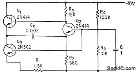
LINEAR_SAWTOOTH_WITH_SPLIT_TIMING_CAPACITOR
Published:2009/7/23 22:49:00 Author:Jessie
To compensate for linearity deterioration, timing capacitor of emitter-coupled mvbr is split info two equal parts, and feed, back resistor is connected between center point and emitter of constant-current generator Q3.-B. Rakovic, One More Transistor Makes c linear Sawtooth, Electronics, 35:49, p 50-51. (View)
View full Circuit Diagram | Comments | Reading(512)
Function_generator
Published:2009/7/23 22:48:00 Author:Jessie
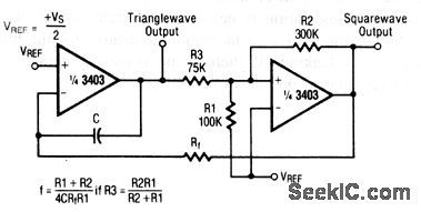
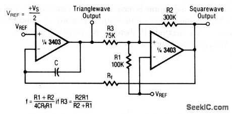
This circuit uses two sections of a 3403 op amp. The frequency of the triangle- and square-wave output is set by the values of R1, R2, C, and Rf, as shown. Raytheon Linear Integrated Circuits 1989, p. 4-159 (View)
View full Circuit Diagram | Comments | Reading(0)
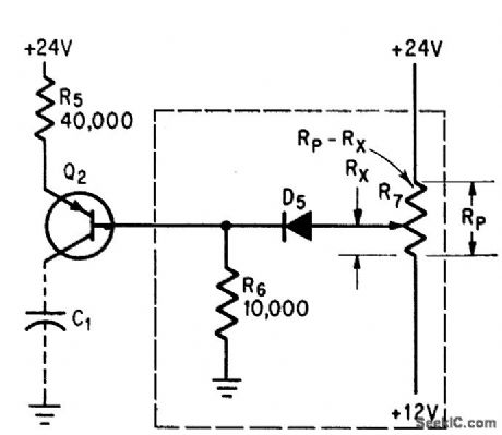
ULTRALINEAR_RAMP_GENERATOR
Published:2009/7/23 22:48:00 Author:Jessie
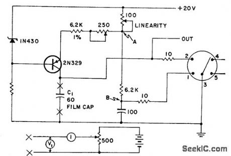
Used in high-accuracy low-speed voltage to pulse width converter. Linearity is better than 0.02% between 10 and 90% points of ramp. Test circuit below is substituted for C1 when adjusting linearity control.-Ultra linear Ramp Generator, Electronic Circuit Design Hand-book, Mactier Pub. Corp., N.Y., 1965, p 166. (View)
View full Circuit Diagram | Comments | Reading(874)
LINEAR_RAMP
Published:2009/7/23 22:48:00 Author:Jessie
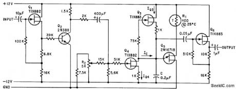
Output voltage varies linearly with frequency within 98%, while peak voltage is constant of 0.6 v. Thermistor R1 provides temperature stability and source follower Q6 reduces loading.-D. D. Brooks and C. F. Johnson, Sawtooth Generator Uses FET as Constant Current Source, Electronics, 38:18, p 87. (View)
View full Circuit Diagram | Comments | Reading(1561)
920_CHANNEL_CRYSTAL_REFERENCE
Published:2009/7/23 22:47:00 Author:Jessie
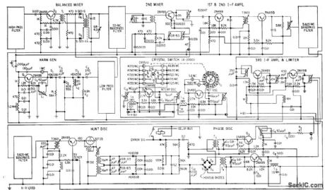
Controlled4equency mobile radio transceiver, operating in two bands, uses improved band. pass filter techniques that double number of channels per megacycle of spectrum, Oscillator-stabilized system is designed for 50-kc channel spacing and selects any of 920 channels between 30 and 76 Mc.-F. Brauer and D. Kammer, Mobile Radio System Provides 920 Channels, Electronics, 31:41, p 96-99. (View)
View full Circuit Diagram | Comments | Reading(550)
TRIANGULAR_WAVEFORM_GENERATOR
Published:2009/7/23 22:47:00 Author:Jessie
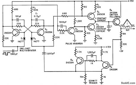
Used in synthesizing waveforms of predetermined shape. Produces single triangular pulse each time it is triggered externally. Output pulse has constant peak amplitude with no flattening, and independently adjustable rise time (R1) and all time (R2). Schmitt trigger Q7-Q8 resets one-shot mvbr Q1-Q2 and limits amplitude of output.-R. G. Teeter, Triangle Waveform Generator Resets Automatically, Electronics, 39:14, p 78. (View)
View full Circuit Diagram | Comments | Reading(771)
BOOSTING_SAWTOOTH_FREQUENCY
Published:2009/7/23 22:30:00 Author:Jessie
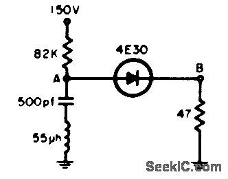
Inductor causes ringing and thereby extends operating frequency of sawtooth oscillator using four-layer diode. Will operate well above 100 kc.-P. Emile, Jr., Inductor Raises Useful Sawtooth Frequency, EEE, 12:7, p 28. (View)
View full Circuit Diagram | Comments | Reading(480)
60_KC_HYDROPHONE_RECEIVER
Published:2009/7/23 22:30:00 Author:Jessie

Shore-based receiver responds to four signal frequencies in 60-kc region, at levels as low as 1 microvolt, coming from receiving hydrophone through up to 15,000 feet of 120-ohm underwater cable. Output of cathode follower V6B is connected to four Foster-Seeley discriminators (not shown) that demodulate signals for driving recorder. Used in monitoring performance of four underwater mines while test ship passes over.-M. J. Aucremanne and D. D. Woolston, Telemeter System Relays Undersea Ordnance Data, Electronics, 31:41, p 84-87. (View)
View full Circuit Diagram | Comments | Reading(792)
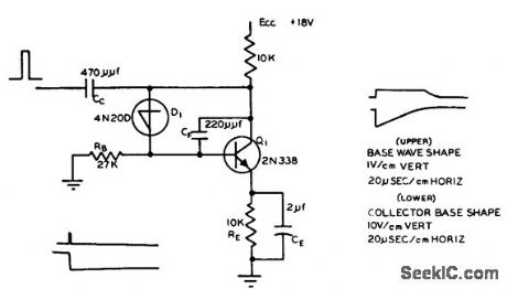
SIMPLE_SAWTOOTH
Published:2009/7/23 22:30:00 Author:Jessie
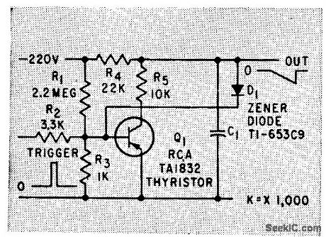
Uses semiconductor switch Q1, whose amplitude is controlled by zener diode D1. Operation on only small part of R-C charging curve helps make out put pulse widths, amplitudes, and waveform timing independent of active elements in circuit.-C. A. Von Urff and R. W. Ahrons, How to Generate Accurate Sawtoolh and Pulse Waves, Electronics, 32:50, p 64-66. (View)
View full Circuit Diagram | Comments | Reading(520)
PULSE_WIDTH_MEASUREMENT
Published:2009/7/23 22:29:00 Author:Jessie
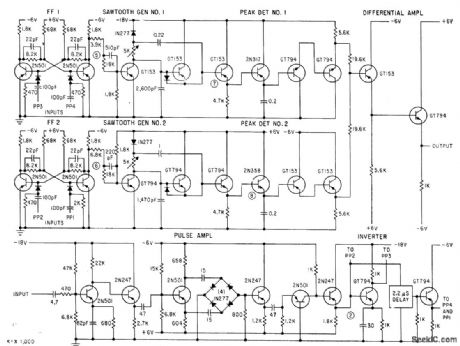
Develops two sawtooth waveforms of equal slope, one delayed relative to other by width of pulse to be measured. Control flip-flops turn both sawtooth generators off simultaneously, so difference in sawtooth peak amplitudes is proportional to pulse width being measured.-D. B. Dobson and L. L. Wolff, Automatic Test Equipment Checks Missile Systems, Electronics, 33:29, p 74-78. (View)
View full Circuit Diagram | Comments | Reading(630)
5_HOUR_RAMP
Published:2009/7/23 22:41:00 Author:Jessie
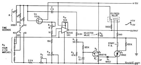
Switches S1 and S2 give ramp periods of 100 to 4,000 sec. Changing C to 10 mid increases period to 20,000 sec. For 5-hour period, C must be 10-mfd low-leakage capacitor. R1 calibrates ramp amp litude and R2 calibrates period.-R. Chapman Period of Sawtooth Ramp Extends to 5 Hours, Electronics, 39:13, p 78. (View)
View full Circuit Diagram | Comments | Reading(496)
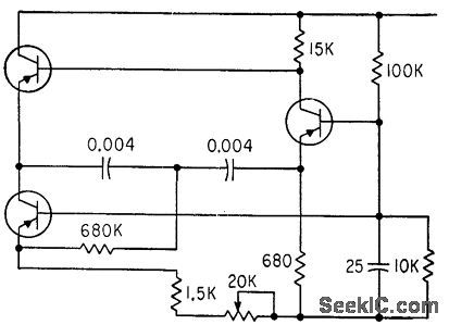
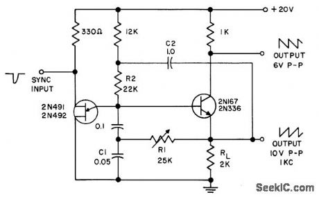
ALL_WAVEFORM_GE_N_ERATOR
Published:2009/7/23 22:40:00 Author:Jessie
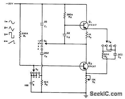
Two-transistor circuit with function switch provides choice of four different waveforms: sine, triangular, square, and sawtooth. Frequency is around 450 cps.-Transistorized All-Waveform Generator, Electronics Circuit Design Handbook, Mactier Pub. Corp., N.Y., 1965, p 168. (View)
View full Circuit Diagram | Comments | Reading(643)
WIDE_RANGE_LINEAR_BOOTSTRAP_TIME_BASE
Published:2009/7/23 22:39:00 Author:Jessie

Delivers highly linear ramps at repetition roles up to 5 Mc, for input pulses from 0.1 microsec to several seconds wide. Nonlinearity is 5% for slow ramps, and improves to 0.05% for fast ramp. Measures pulse width accurately when used in combination with voltage comparator. Can also be used for sampling and for testing amplitude response of linear amplifiers.-T. Mollinga, A Wide-Range, Linear Time Base, EEE, 10:8, p 56-59. (View)
View full Circuit Diagram | Comments | Reading(613)
TRIGGERED_SAWTOOTH
Published:2009/7/23 22:43:00 Author:Jessie
Uses Shockley four-layer diode and transistorized integrating circuit. Ramp starts with quick drop, then rises back to steady-state condition. Pulse width is 0.2 microsec at 400 pps.-Triggered Sawtooth Generator, Electronic Circuit Design Handbook, Mactier Pug. Corp., N.Y., 1965, p 169. (View)
View full Circuit Diagram | Comments | Reading(620)
UNIJUNCTION_SAWTOOTH
Published:2009/7/23 22:42:00 Author:Jessie
Uses ZJ14 unijunction transistor. R1 represents input impedance of conventional emitter-follower having nominal 5,000.ohm impedance in emitter circuit. R3 is 3K and R4 is 330 ohms.-M. Rosen, Subaudio Swept Signal Generator, Electronics, 33:17, p 67-68. (View)
View full Circuit Diagram | Comments | Reading(563)
100__to_300_MHz_frequency_tripler
Published:2009/7/23 22:26:00 Author:Jessie
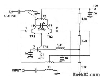
This circuit shows an SL2365 transistor array (Fig. 2-35B) connected as a frequency tripler, with a gain of -40 dB, an input-frequency rejection of 30 dB, and second-harmonic rejection of 28 dB. (View)
View full Circuit Diagram | Comments | Reading(635)
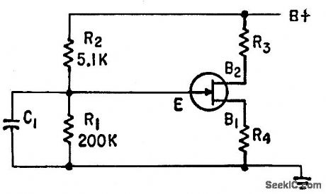
CONSTANT_CURRENT_GENERATOR
Published:2009/7/23 22:25:00 Author:Jessie
Insures that voltage across charging capacitor of unijunction-transistor timer increases linearly with time. Maximum charging current is about 0.3 mo with 2N2605 for C12 and 1N643 for D5. R7 is 1,000-ohm potentiometer.-A. A. Lampell, Off-the-Shelf Integrated Circuits for Versatile and Accurate Timer, Electronics, 38:25, p 70-73. (View)
View full Circuit Diagram | Comments | Reading(3)
HIGH_LINEARITY_SAWTOOTH
Published:2009/7/23 22:25:00 Author:Jessie
Requires only single positive supply. Npn transistor serves as output buffer amplifier, while R2 and C2 in bootstrap circuit improve linearity of saw tooth. R1 and C1 act as integrating network to provide second. order compensation for nonlinearity of waveform.- Transistor Manual, Seventh Edition, General Electric Co., 1964, p 319. (View)
View full Circuit Diagram | Comments | Reading(794)
LINEAR_SAWTOOTH
Published:2009/7/23 22:34:00 Author:Jessie
Q1 and 02 in emitter-coupled mvbr and constant-current generator Q3 produce sweep having linearity comparable to that of vacuum-tube circuits.-B. Rakovic, One More Transistor Makes a Linear Sawtooth, Electronics, 35:49, p 50-51. (View)
View full Circuit Diagram | Comments | Reading(822)
STROBE_GENERATOR
Published:2009/7/23 22:33:00 Author:Jessie
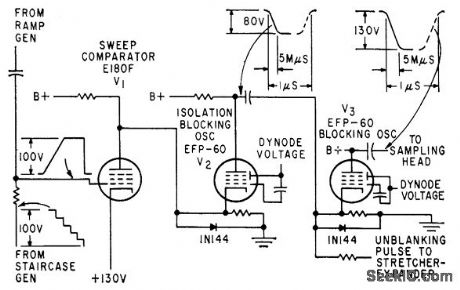
Sweep comparator V1 mixes output of ramp generator and staircase generator to give sampling or strobe pulse. Instantaneous d-c level of ramp, cor responding to a step, fixes time at which strobe signal is generated.-W. E. Bushor, Sample Method Displays Millimicrosecond Pulses, Electronics, 32:31, p 69-71. (View)
View full Circuit Diagram | Comments | Reading(551)
| Pages:115/195 At 20101102103104105106107108109110111112113114115116117118119120Under 20 |
Circuit Categories
power supply circuit
Amplifier Circuit
Basic Circuit
LED and Light Circuit
Sensor Circuit
Signal Processing
Electrical Equipment Circuit
Control Circuit
Remote Control Circuit
A/D-D/A Converter Circuit
Audio Circuit
Measuring and Test Circuit
Communication Circuit
Computer-Related Circuit
555 Circuit
Automotive Circuit
Repairing Circuit