
Index 123
PREFERRED_01_REGU[ATION_250_V_D_C
Published:2009/7/20 5:11:00 Author:Jessie

Provides either polarity, for applications requiring superior regulation and stability. Minimum input is 290 v d-c, and minimum Esg is 150 v d-c. Maximum output is 100 ma per series lube. C4 is minimum of 4 mfd.-NBS, Handbook Preferred Circuits Navy Aeronautical Electronic Equipment, Vol. 1, Electron Tube Circuits, 1963, PC 8, p 8-2.
(View)
View full Circuit Diagram | Comments | Reading(838)
10_KV_R_F_OSCILLATOR_TYPE_CRT_SUPPLY
Published:2009/7/20 5:09:00 Author:Jessie

Associated regulator controls oscillator output. Considered less desirable than a-f oscillator supplies, which have no r-f radiation problem.-NBS, Handbook Preferred Circuits Navy Aeronautical Electronic Equipment, Vol. 1, Electron Tube Circuits, 1963, p N14-3. (View)
View full Circuit Diagram | Comments | Reading(637)
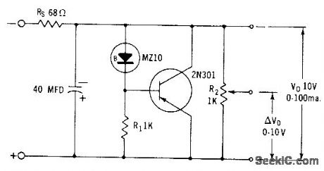
UJT_SCR_REGULATED_A_C_SUPPLY
Published:2009/7/20 5:08:00 Author:Jessie

Component values shown give optimum regulation at 25 v rms output, with less than 0.1 v variation for change in line voltage from 115 v to 100 v. For wider range of output voltage than 10 to 30 v, R1 and R4 can be ganged pot.- Transistor Manual, Seventh Edition, General Electric Co., 1964, p 334. (View)
View full Circuit Diagram | Comments | Reading(798)
REMOTELY_ADJUSTABLE_SOLID_STATE_HIGH_VOLTAGE_SUPPLY
Published:2009/7/9 4:43:00 Author:May
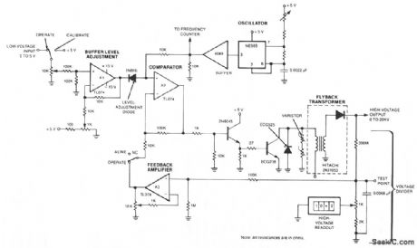
The output voltage changes approximately linearly up to 20 KV as the input voltage is varied from 0 to 5 V. The oscillator is tuned by a 5-Ω potentiometer to peak the output voltage at the frequency of maximum transformer response between 45 and 55 kHz. The feedback voltage is applied through a 100-KΩ resistor, an op amp, and a comparator to a high-voltage amplifier. A diode and varistors on the primary side of the transformer protect the output transistor. The transformer is a flyback-type used in color-television sets. A feedback loop balances between the high-voltage output and the low-voltage input. (View)
View full Circuit Diagram | Comments | Reading(728)
TRIAC_UJT_PHASE_CONTROL
Published:2009/7/20 6:22:00 Author:Jessie

Provides wide range of stable control without hysteresis at low outputs and without dependence on supply voltage. Triac eliminates need for transient suppression components that would be required with scr control and permits use of simple two-winding pulse transformer.-M. P. Southworth, Bidirectional Static Switch Simplifies A-C Control, Control Engineering, March 1964, p 75-76. (View)
View full Circuit Diagram | Comments | Reading(800)
1_out_of_32_multiplexer_using_two_IH6116s_and_one_IH5041
Published:2009/7/20 6:23:00 Author:Jessie

1-out-of-32 multiplexer using two IH6116s and one IH5041. The IH6116s are CMOS 16-channel analog multiplexers (courtesy Intersil, Inc.). (View)
View full Circuit Diagram | Comments | Reading(545)
2_levei_8_channel_multiplexor
Published:2009/7/20 6:25:00 Author:Jessie

2-levei 8-channel multiplexor (courtesy Motorola Semiconductor Products Inc.). (View)
View full Circuit Diagram | Comments | Reading(562)
152_V_PENTODE_SERIES_TUBE_REGULATOR
Published:2009/7/20 7:11:00 Author:Jessie

Has excellent frequency response, but this performance could also be obtained if cath. ode follower were amplifier using negative feedback for frequency compensation, dong with better regulation and lower d-c resislance.-NBS, Handbook Preferred Circuits Navy Aeronautical Electronic Equipment, Vol. 1, Electron Tube Circuits, 1963, p N2-11. (View)
View full Circuit Diagram | Comments | Reading(1042)
PREFERRED_250_V_D_C_REGULATOR
Published:2009/7/20 7:09:00 Author:Jessie

Provides either polarity of output with 1% regulation, from minimum of 300 v d-c. C5 is minimum of 4 mfd.-NBS, Handbook Preferred Circuits Navy Aeronautical Electronic Equipment, Vol. 1, Electron Tube Circuits, 1963, PC 7, p 7-2. (View)
View full Circuit Diagram | Comments | Reading(655)
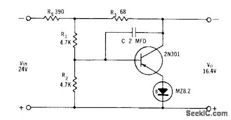
REMOTE___SENSING_6_V_REGULATOR
Published:2009/7/20 7:07:00 Author:Jessie

Used when small lead resistance between regulator and load is physically impossible. Voltage Eo' is essentially voltage that appears directly across load. Differential amplifier senses and corrects for changes in this volt-age rather thon for changes in Eo at regulator output terminals.-NBS, Handbook Preferred Circuits Navy Aeronautical Electronic Equipment, Vol. 11, Semiconductor Device Circuits, PSC 1, p 1-11. (View)
View full Circuit Diagram | Comments | Reading(707)
DARLINGTON_CONNECTED_SERIES_REGULA_TOR
Published:2009/7/20 7:04:00 Author:Jessie

Designed for output currents up to 2 amp average or 3.5 amp peak. Output voltage can be adjusted from 45 to 65 v by R7. Ripple is less than 1 my rms at no load, increasing to 60 my peak-to-peak at 2 amp. Regulation is 2.1% at 2 amp and 0.72% at 1 amp.- Transistor Manual, Seventh Edition, General Electric Co., 1964, p 228. (View)
View full Circuit Diagram | Comments | Reading(646)
SIMPLE_HIGH_VOLTAGE_SUPPLY
Published:2009/7/9 4:21:00 Author:May

This circuit can generate high-voltage pulses with an inexpensive auto ignition coil. Add a rectifier on the output and the circuit produces high-voltage dc. The circuit's input is 115 Vac. During the input's positive half cycle, energy is stored in capacitor C1, which is charged via diode D1 and the primary winding of transformer T1, the coil. The SCR and its trigger circuitry are inactive during this period. During the input's negative half cycle, energy is stored in capacitor C2 until diac D2 reaches its trigger voltage, whereupon D2 conducts abruptly and C2 releases its energy into the SCR's gate. The SCR then discharges C1 into the transformer's primary and ceases to conduct. This store-and-release cycle repeats on the line's positive and negative half cycles, producing high-voltage pulses at the transformer's secondary. (View)
View full Circuit Diagram | Comments | Reading(0)
8_V_VOLTAGE_REGULATOR
Published:2009/7/20 6:48:00 Author:Jessie
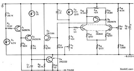
Output voltage is held within 0.1% despite 5-v variations in 20-v input to regulator that itself consumes only 1.5 ma. Differential amplifier Q5 acts as voltage comparator, with zener diode D3 as reference.-A. Dargis, A High Performance Voltage Regulator, Electronics, 37:13, p 75. (View)
View full Circuit Diagram | Comments | Reading(623)
SHUNT_REGULATOR_1
Published:2009/7/20 6:46:00 Author:Jessie
Used when output can be less than zener voltage.- Zener Diode Handbook, International Rectifier Corp., 1960, p 55. (View)
View full Circuit Diagram | Comments | Reading(680)
PREREGULATED_HIGH_VOLTAGE_SUPPLY
Published:2009/7/9 4:09:00 Author:May
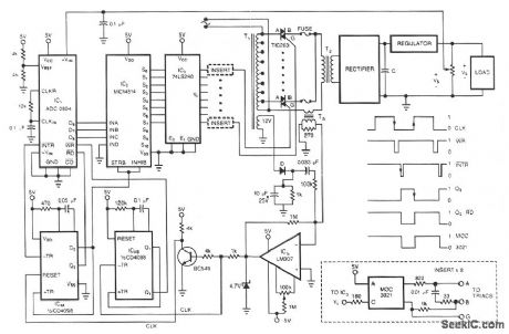
One of the control circuit's triacs selects the tap on main transformer T1, which provides the proper, preregulated voltage to the secondary regulator. T2 and its associated components comprise the second-ary regulator.The ADO 0804, IC1, digitizes a voltage-feedback signal from the secondary regulator's output. The MC1415 demultiplexer, IC2, decodes the digitizer's output. IC2, in turn, drives T1's optoisolated triacs via the 74LS240 driver chip, IC3, and associated optoisolators.Transformer T3 samples the circuit's current output. The auxiliary, 12 V winding on T1 ensures no-load starting. The combination of op amp IC5 and the inverting transistor, Q1, square this current signal. The output of Q1 is the CLK signal, which triggers one-half of the one shot, IC4A, to begin the circuit's A/D conversion. The one shots' periods are set to time out within 1/2 cycle of the ac input.Upon completion of its A/D conversion, IC1's INTR output triggers the other half of the one shot, IC4B, which enables the converter's data outputs. The rising edge of the CLK signal resets the one shot and latches the new conversion value into IC2. The latch, associated driver, and optoisolator trigger a selected triac according to the latest value of the voltage-feedback signal, VO. (View)
View full Circuit Diagram | Comments | Reading(1234)
UNINTERRUPTABLE__5_V_SUPPLY
Published:2009/7/9 4:02:00 Author:May
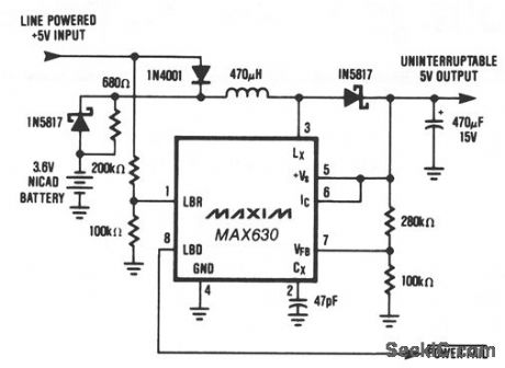
This circuit provides a continuous supply of regulated + 5 V, with automatic switch-over between line power and battery backup. When the line-powered input voltage is a +5 V, it provides 4.4 V to the MAX630 and trickle charges the battery. If the line-powered input falls below the battery voltage, the 3.6 V battery supplies power to the MAX630, which boosts the battery voltage up to + 5 V, thus maintain-ing a continuous supply to the uninterruptable + 5 V bus. Since the + 5 V output is always supplied through the MAX630, there are no power spikes or glitches during power transfer. The MAX630's low-battery detector monitors the line-powered +5 V, and the LBD output can be used to shut down unnecessary sections of the system during power failures. Alternatively, the low-battery detector could monitor the NiCad battery voltage and provide warning of power loss when the battery is nearly discharged. Unlike battery backup systems that use 9-V batteries, this circuit does not need + 12 or + 15 V to recharge the battery. Consequently, it can be used to provide + 5 V backup on modules or circuit cards which only have 5 V available. (View)
View full Circuit Diagram | Comments | Reading(617)
150_AND_300_V_SERIES_TUBE_REGULATOR
Published:2009/7/20 6:45:00 Author:Jessie
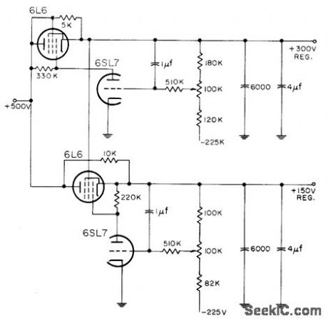
Uses simple triode as regulator amplifier. Series tube for 300.v supply is conventional triode-connected pentode, but series tube that regulates 150 v has its screen fed from output of 300-v regulated supply, for pentode operation.-NBS, Handbook Preferred Circuits Navy Aeronautical Electronic Equipment, Vol. 1, Electron Tube Circuits, 1963, p N2-11. (View)
View full Circuit Diagram | Comments | Reading(1623)
THERMOCOUPLE_VACUUM_GAGE_HEATER
Published:2009/7/20 6:43:00 Author:Jessie

Simple regulator for 240-v d-c supply provides 140 mc with 0.1% regulation. Uses regulator triode, pentode-connected d-c amplifier, and series-connected reference regulator tube.-W. V. Loebenstein, Regulated Power Supply for Instruments, Electronics, 33:48, p 132. (View)
View full Circuit Diagram | Comments | Reading(2104)
SHUNT_REGULATOR
Published:2009/7/20 6:41:00 Author:Jessie
Used when output volt-age must be higher than zener voltage. Rip-ple is less than 10 my when regulator is supplied by full-wove rectifier having 20 mid capacitance.- Zener Diode Handbook, In ternational Rectifier Corp., 1960, p 55. (View)
View full Circuit Diagram | Comments | Reading(784)
SINGLE_SUPPLY_FREQUENCY_VOLTAGE_CONVERTER
Published:2009/7/9 3:40:00 Author:May
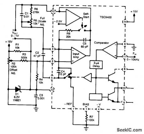
A Teledyne TSC9400 provides 0-to-1-V output from a 0-to-10-kHz input.A single +15-V supply is used,Linearity is 0.25% to 10 kHz. (View)
View full Circuit Diagram | Comments | Reading(801)
| Pages:123/291 At 20121122123124125126127128129130131132133134135136137138139140Under 20 |
Circuit Categories
power supply circuit
Amplifier Circuit
Basic Circuit
LED and Light Circuit
Sensor Circuit
Signal Processing
Electrical Equipment Circuit
Control Circuit
Remote Control Circuit
A/D-D/A Converter Circuit
Audio Circuit
Measuring and Test Circuit
Communication Circuit
Computer-Related Circuit
555 Circuit
Automotive Circuit
Repairing Circuit