
Index 125
Remote_shutdown_regulator+5_voltswith_current_limiting_using_an_ECG915_
Published:2009/7/20 20:46:00 Author:Jessie
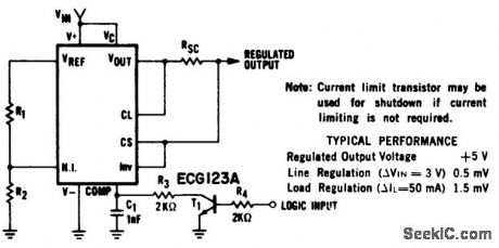
Remote shutdown regulator(+5 volts)with current limiting using an ECG915 or ECG915D.For a ±5% fixed output resistor R1 is 2,15 ohms and R2 is 4.99 ohms.Resistor RSC is 10 ohms(courtesy GTE Sylvania Incorporated). (View)
View full Circuit Diagram | Comments | Reading(754)
Positive_voltage_regulators_for_5_6_12_15_or_24_volts_using_the_ECG9XX_series
Published:2009/7/20 20:44:00 Author:Jessie
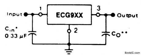
Positive voltage regulators for 5, 6, 12, 15, or 24 volts using the ECG9XX series.Rating for the three-terminal ECG9XX positive voltage regulators are as follows: ECG960, 5 volts; ECG962, 6 volts; ECG966, 12 volts; ECG968, 15 volts; and ECG972, 24 volts. A common ground is required between the input and output voltages. The input voltage must remain typically 2 volts above the output voltage even during the low point on the ripple (courtesy GTE Sylvania Incorporated). (View)
View full Circuit Diagram | Comments | Reading(577)
First_and_second_mixer_stages_for_a_27_MHz_CB_receiver
Published:2009/7/20 23:34:00 Author:Jessie
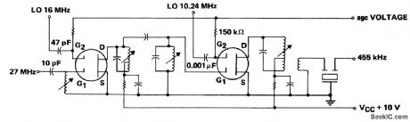
First and second mixer stages for a 27 MHz CB receiver. Note that these two stages replace three in conventional receivers not employing dual-gate MOSFETs (courtesy Texas Instruments Incorporated). (View)
View full Circuit Diagram | Comments | Reading(578)
250_KW_PEAK_FROM_SCR
Published:2009/7/20 23:32:00 Author:Jessie
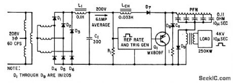
Line-type modulator uses silicon diodes for high-voltage rectifiers, backswing, holdoff, and inverse-diode circuits. Trigger generator uses two-layer and four-layer diodes to provide pulse burst repetition rates up to 25 kc.-H. G. Heard, Controlled Rectifier Produces Quarter-Mega watt Pulse Power, Electronics, 34:25, p 54-55. (View)
View full Circuit Diagram | Comments | Reading(632)
5_volt_40_ampere_power_inverter_supply
Published:2009/7/20 21:34:00 Author:Jessie

5-volt 40-ampere power inverter supply (courtesy Motorola Semiconductor Products Inc.). (View)
View full Circuit Diagram | Comments | Reading(1278)
SERIES_REGULATION_AT_3_V
Published:2009/7/20 21:32:00 Author:Jessie
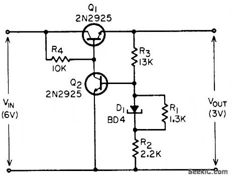
Combination of backward diode and resistor network serves as reference for regulated outputs below 6 v, for which temperature -compensated zener diodes are not available. Provides input regulation of 100:1 over 10% change in input voltage, with output impedance of 0.04 ohm. -T. P. Sylvan, Backward-Diode Power-Supply Reference Elements, EEE, 13:11, p 46-48. (View)
View full Circuit Diagram | Comments | Reading(551)
Digitally_programmed_power_supply
Published:2009/7/20 21:31:00 Author:Jessie

Digitally programmed power supply. A D/A convener with an op amp supplies voltage in accordance with a digital code (courtesy Analog Devices, Inc.). (View)
View full Circuit Diagram | Comments | Reading(617)
THYRATRON_REGULATOR
Published:2009/7/20 21:30:00 Author:Jessie

Output of 12 to 16 v is regulated within 1% for loads of 6 to 22 ma. Since 2D21 can handle 100 ma continuously, circuit is easily modified to regulate higher current values.-W. D. Fryer, Thyratron Regulates Supply, Electronics, 31: 25, p 88. (View)
View full Circuit Diagram | Comments | Reading(698)
Direct_line_operated_power_supply_for_line_operated_servo_amplifier
Published:2009/7/20 21:30:00 Author:Jessie
Direct-line-operated power supply for line-operated servo amplifier (courtesy Motorola Semiconductor Products Inc.). (View)
View full Circuit Diagram | Comments | Reading(483)
VOLTAGE_SPLITTER_REGULATOR
Published:2009/7/20 21:29:00 Author:Jessie
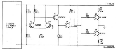
Provides regulated +12 and -12 v from 24-v supply Negative feedback loop permits circuit to furnish unbalanced currents up to 700 ma in either direction without changing output voltages more than 10 my.-J. M. Kasson, Voltage Splitter Balances Floating Power Supply, Electronics, 39:6, p 96. (View)
View full Circuit Diagram | Comments | Reading(1449)
10_volt_reference_with_4_ampere_capacity_using_an_AD581_and_a_2N6040
Published:2009/7/20 21:29:00 Author:Jessie
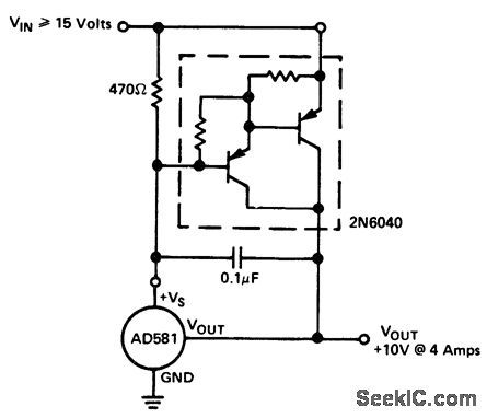
10-volt reference with 4-ampere capacity using an AD581 and a 2N6040 (courtesy Analog Devices, Inc.). (View)
View full Circuit Diagram | Comments | Reading(900)
Power_supply_for_line_operated_servo_amplifier_using_a_power_transformer
Published:2009/7/20 21:28:00 Author:Jessie
Power supply for line-operated servo amplifier using a power transformer (courtesy Motorola Semiconductor Products Inc.). (View)
View full Circuit Diagram | Comments | Reading(474)
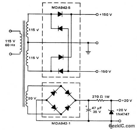
24_volt_DC_regulated_power_supply_with_500_mA_rating
Published:2009/7/20 21:06:00 Author:Jessie
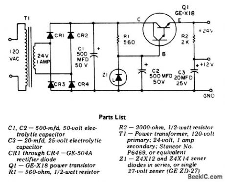
24-volt DC regulated power supply with 500 mA rating. Output ripple is less than 4.5 mV. R2 can be changed to obtain other secondary output voltages as desired (courtesy General Electric Company). (View)
View full Circuit Diagram | Comments | Reading(636)
Variable_output_voltage_regulator_using_the_μA79HG_which_can_supply_a_minimum_of_5_amperes_at_voltages_from__23_volts_to__24_volts
Published:2009/7/20 21:05:00 Author:Jessie

Variable output voltage regulator using the μA79HG, which can supply a minimum of 5 amperes at voltages from -2.3 volts to -24 volts (courtesy Fairchild Semiconductor). (View)
View full Circuit Diagram | Comments | Reading(555)
Step_down_switching_regulator_using_an_SH1605
Published:2009/7/20 21:04:00 Author:Jessie
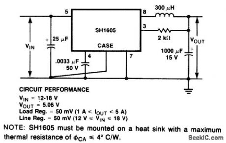
Step-down switching regulator using an SH1605. Output voltage is +5 volts. Available current is between 1 and 5 amperes. Input voltage is 12 to 18 volts. Line regulation is 2% with load regulation at 2%. Maximum ripple is 0.1 volt peak to peak (courtesy Fairchild Semiconductor). (View)
View full Circuit Diagram | Comments | Reading(530)
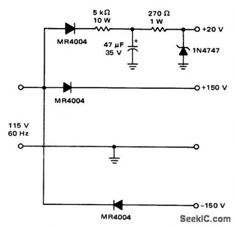
Programmable_power_supply_with_±100_volt_and_±50_volt_output
Published:2009/7/20 21:03:00 Author:Jessie
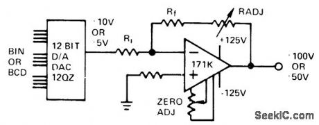
Programmable power supply with ±100-volt and ±50-volt output (courtesy Analog Devices, Inc.). (View)
View full Circuit Diagram | Comments | Reading(491)
HUM_FREE_TUNER_SUPPLY
Published:2009/7/8 23:49:00 Author:May

Permits operation of high-quality FM tuner from amplifier supply without having hum due to positive feedback through shared ground connection.Circuit provides up to 90 mA at 12 V from any supply ranging from 24 to 34 V. Low output impedance eliminates all likely sources of feed-back and suppresses ripple. Circuit requires careful initial adiustment to limit current sunk by 741C opamp to Iess than 15 mA; coarse adjustment is made by varying number of 47-ohm resistors in parallel serving as BD136 omitter re-sistor, and fine adjustment by changing R2.-G.Hibbert, Avoiding Power Supply Hum, Wireless Wolld, Oct. 1973, p 515. (View)
View full Circuit Diagram | Comments | Reading(517)
10_volt_reference_from_a_12_volt_suppy
Published:2009/7/20 20:58:00 Author:Jessie
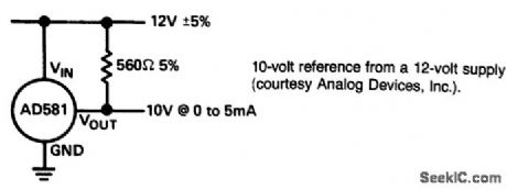
10-volt reference from a 12-volt suppy(courtesy Analog Devices,Inc.). (View)
View full Circuit Diagram | Comments | Reading(486)
CONDUCTIVITY_METER
Published:2009/7/20 20:57:00 Author:Jessie

Circuit using single quad opamp measures relative change in con-centration of salt solution by monitoring its conductance. Use of alternating current through solution eliminates errors caused by electrolysis effect. Wien-bridge oscillator having R4C1 and R4R3 as arms of bridge generates 1-kHz signal for driving amplifier A2 through solution. P1 controls oscillator amplitude, and P2 adjusts gain of A2. A3-A4 form precision rectifier giving output voltage equal to absolute value of input voltage.-M. Ahmon, One-Chip Conductivity Meter Monitors Salt Concentration, Electronics, Sept. 15, 1978, p 132-133. (View)
View full Circuit Diagram | Comments | Reading(9756)
Precision_10_volt_reference_with_fine_trim_adjustment
Published:2009/7/20 20:56:00 Author:Jessie
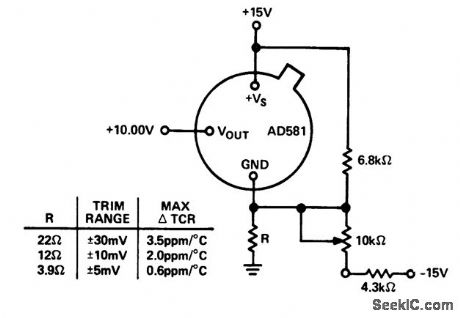
Precision 10-volt reference with fine trim adjustment (courtesy Analog Devices, Inc.). (View)
View full Circuit Diagram | Comments | Reading(595)
| Pages:125/291 At 20121122123124125126127128129130131132133134135136137138139140Under 20 |
Circuit Categories
power supply circuit
Amplifier Circuit
Basic Circuit
LED and Light Circuit
Sensor Circuit
Signal Processing
Electrical Equipment Circuit
Control Circuit
Remote Control Circuit
A/D-D/A Converter Circuit
Audio Circuit
Measuring and Test Circuit
Communication Circuit
Computer-Related Circuit
555 Circuit
Automotive Circuit
Repairing Circuit