
Index 122
12_volt_power_supply_using_an_over_winding_from_a_phonograph_motor
Published:2009/7/20 5:32:00 Author:Jessie
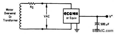
12-volt power supply using an over winding from a phonograph motor. With 16 volts AC the output is approximately 12 volts DC. Rs is the series resistance of the winding (courtesy GTE Sylvania Incorporated). (View)
View full Circuit Diagram | Comments | Reading(595)
Voltage_boosted_40_volt_100_mA_regulator_with_short_circuit_current_limiting_
Published:2009/7/20 5:32:00 Author:Jessie
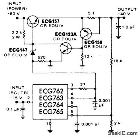
Voltage-boosted 40-volt 100 mA regulator with short-circuit current limiting (courtesy GTE Sylvania Incorporated). (View)
View full Circuit Diagram | Comments | Reading(552)
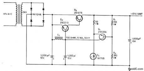
15_volt_1_ampere_regulator_with_short_circuit_protection
Published:2009/7/20 5:30:00 Author:Jessie
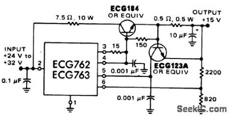
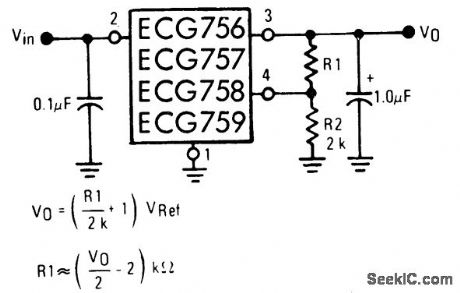
15-volt 1-ampere regulator with short-circuit protection (courtesy GTE Sylvania Incorporated). (View)
View full Circuit Diagram | Comments | Reading(482)
15_volt_regulator
Published:2009/7/20 5:30:00 Author:Jessie
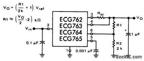
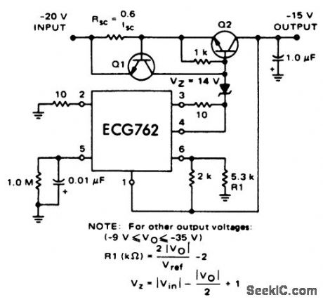
15-volt regulator. Input voltage for ECG762 and ECG763 should not exceed 38 volts and for the ECG764 and ECG765 should not exceed 22 volts (courtesy GTE Sylvania Incorporated). (View)
View full Circuit Diagram | Comments | Reading(568)
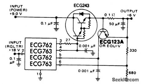
5_volt_5_ampere_regulator_with_remote_sensing_PNP_current_boost
Published:2009/7/20 5:29:00 Author:Jessie
5-volt 5-ampere regulator with remote sensing PNP current boost (courtesy GTE Sylvania Incorporated). (View)
View full Circuit Diagram | Comments | Reading(601)
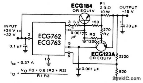
15_volt_regulator_with_current_limit
Published:2009/7/20 5:27:00 Author:Jessie
15-volt regulator with current limit (courtesy GTE Sylvania Incorporated). (View)
View full Circuit Diagram | Comments | Reading(558)
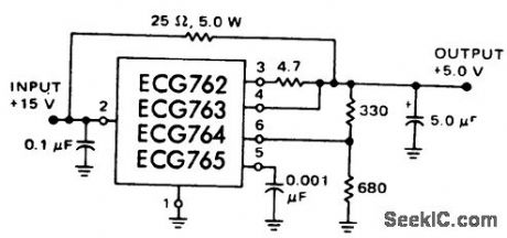
5_volt_regulator
Published:2009/7/20 5:27:00 Author:Jessie
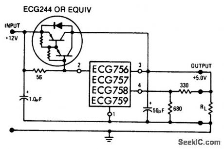
5-volt regulator. Input voltage should not exceed 22 volts for the ECG758 and ECG759 or 38 volts for the ECG756 and ECG757. All of these units are 4-lead packages (courtesy GTE Sylvania Incorporated). (View)
View full Circuit Diagram | Comments | Reading(478)
100_W_SWITCHING_REGULATOR
Published:2009/7/20 5:43:00 Author:Jessie
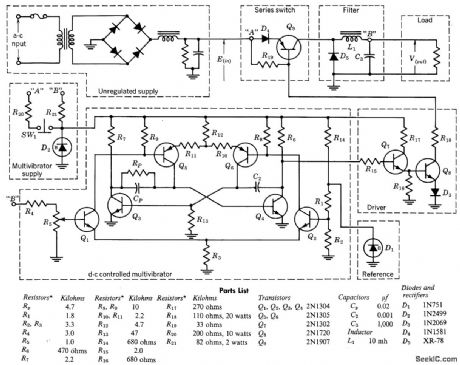
Chief advantage of switching-mode regulator is relatively low power dissipated in series regulating transistor. Circuit provides 20 v d-c output, constant within 0.2 v, for loads up to 5 amp. Input 60-cps voltage may vary 10 v above and below 40 v. Operating tempera lure range is -25 to +50°C. Driver transistors Q7 and Q8 operate as switches that are saturated when driven with positive pulses from mvbr.-Texas Instruments Inc., Transistor Circuit Design, McGraw-Hill, N.Y., 1963, p 468. (View)
View full Circuit Diagram | Comments | Reading(760)
NEGATIVE_OUTPUT_150_AND_300_V_REGU_LATOR
Published:2009/7/20 5:41:00 Author:Jessie

Operation is comparable to tortes ponding positive-output circuit.-NBS, Hand-book Preferred Circuits Navy Aeronautical Electronic Equipment, Vol, 1 Electron Tube Circuits, 1963, p N2-5. (View)
View full Circuit Diagram | Comments | Reading(601)
NEGATIVE_OUTPUT_250V_REGULATOR
Published:2009/7/20 5:39:00 Author:Jessie
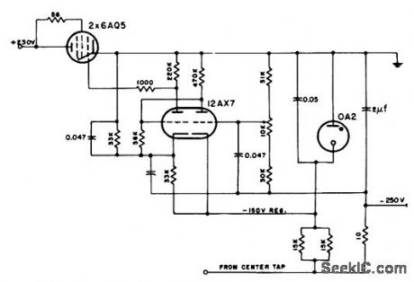
Operation is comparable to corresponding positive-output circuit.-NBS, Handbook Preferred Circuits Navy Aeronautical Electronic Equipment, Vol. 1, Electron Tube Circuits, 1963, p N2-5. (View)
View full Circuit Diagram | Comments | Reading(602)
5_volt_5_ampera_regulator_with_remote_sensing_and_PNP_current_boost
Published:2009/7/20 5:38:00 Author:Jessie

5-volt 5-ampera regulator with remote sensing and PNP current boost (courtesy GTE Sylvania Incorporated). (View)
View full Circuit Diagram | Comments | Reading(614)
100_mA_constant_current_source
Published:2009/7/20 5:36:00 Author:Jessie
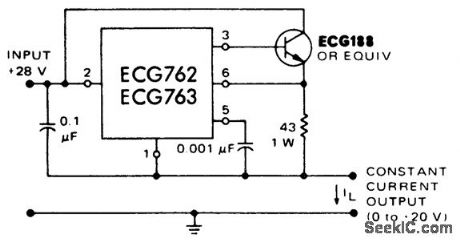
100 mA constant-current source (courtesy GTE Sylvania Incorporated). (View)
View full Circuit Diagram | Comments | Reading(768)
Current_bypass_with_load_current_from_400_to_500_mA_
Published:2009/7/20 5:36:00 Author:Jessie
Current bypass with load current from 400 to 500 mA (courtesy GTE Sylvania Incorporated). (View)
View full Circuit Diagram | Comments | Reading(495)
6_volt_5_ampere_high_efficiency_regulator
Published:2009/7/20 5:35:00 Author:Jessie
6-volt 5-ampere high-efficiency regulator (Courtesy GIF Sylvania Incorporated). (View)
View full Circuit Diagram | Comments | Reading(643)
15_volt_2_ampere_regulator_with_current_foldback_
Published:2009/7/20 5:34:00 Author:Jessie
15-volt 2-ampere regulator with current foldback (courtesy GTE Sylvania Incorporated). (View)
View full Circuit Diagram | Comments | Reading(593)
12_volt_power_supply_using_an_over_winding_of_a_phonograph_motor_or_a_transformer
Published:2009/7/20 5:33:00 Author:Jessie
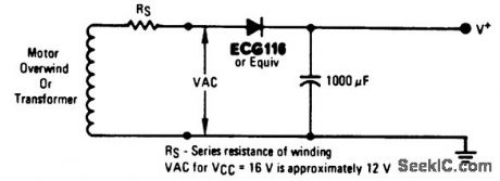
12-volt power supply using an over winding of a phonograph motor or a transformer. With 16 volts AC, the output will be approximately 12 volts DC. Rs is the series resistance of the winding (courtesy GTE Sylvania Incorporated). (View)
View full Circuit Diagram | Comments | Reading(594)
FEEDBACK_CHOKE_CUIS_RIPPLE
Published:2009/7/20 5:24:00 Author:Jessie
Choke L1, placed in feedback path from Q1 to Q2, holds down ripple in current supplied to load through Darlington amplifier Q2-Q3. Choke acts as if it were in series with load even though carrying only a fraction of load current.-J. T. Quatse, Feedback Choke Reduces Power Supply Ripple, Electronics, 39:13, p 74. (View)
View full Circuit Diagram | Comments | Reading(583)
12_V_D_C_REGULATOR
Published:2009/7/20 5:23:00 Author:Jessie

Provides up to 3 amp at 12 v with 1% regulation for inputs of 13 to 50 v from unregulated source. Auxiliary source Ea must be minimum of 5 v.-NBS, Handbook Preferred Circuits Navy Aeronautical Electronic Equipment, Vol. 11, Semiconductor Device Circuits, PSC 2, p 2-4. (View)
View full Circuit Diagram | Comments | Reading(550)
PRECISION_12_V_200_MA_SUPPLY
Published:2009/7/20 5:21:00 Author:Jessie
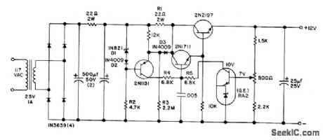
Regulation is less than 0.001% for 10% change in line voltage. Sharp current limiting at 300 ma is provided by R1 and D3. Darlington connection for series regulator gives current gain of 10,000 at 100 ma, so normal variation of reference amplifier collector current is only 10 microamp over full range of output current.- Iransistor Manual, Seventh Edition, General Electric Co., 1964, p 232. (View)
View full Circuit Diagram | Comments | Reading(564)
75_watt_AF_power_amplifier_with_low_transient_intermodulation_distortion
Published:2009/7/20 5:16:00 Author:Jessie


75-watt AF power amplifier with low-transient-intermodulation distortion (courtesy Fairchild Semiconductor). (View)
View full Circuit Diagram | Comments | Reading(1615)
| Pages:122/291 At 20121122123124125126127128129130131132133134135136137138139140Under 20 |
Circuit Categories
power supply circuit
Amplifier Circuit
Basic Circuit
LED and Light Circuit
Sensor Circuit
Signal Processing
Electrical Equipment Circuit
Control Circuit
Remote Control Circuit
A/D-D/A Converter Circuit
Audio Circuit
Measuring and Test Circuit
Communication Circuit
Computer-Related Circuit
555 Circuit
Automotive Circuit
Repairing Circuit