
Index 127
Square_rooter_circuit_using_an_AD532_multiplier_divider_chip
Published:2009/7/21 4:35:00 Author:Jessie
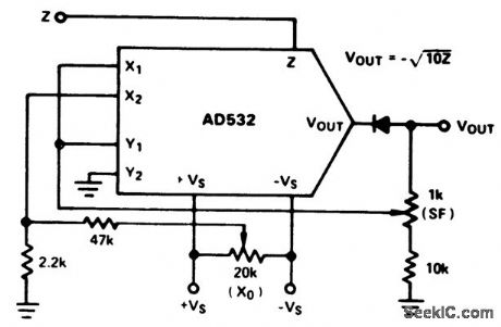
Square rooter circuit using an AD532 multiplier/divider chip. The AD532 is available as a 10-pin TO-100 or as a 14-pin DIP (courtesy Analog Devices,Inc.). (View)
View full Circuit Diagram | Comments | Reading(548)
ANALOG_VOLTAGE_SOURCE
Published:2009/7/21 4:43:00 Author:Jessie
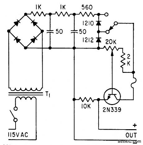
Consists of bridge-rectifier supply with R-C filtering and zener diode regulation, feeding control potentiometer that is isolated from load by grounded-collector transistor. Used as analog voltage source for computer circuit. –E. R. James, Semiconductors Provide Analog Voltage Source, Electronic, 31:33, p 96-100. (View)
View full Circuit Diagram | Comments | Reading(635)
Power Line Carrier Remote Control Switched Circuit
Published:2011/8/1 19:38:00 Author:Zoey | Keyword: Power Line Carrier, Remote Control, Switched Circuit
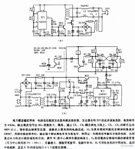
This circuit is composed of carrier transmitter and carrier receiver. The transmitter uses a 555 and is jionted to be a multi-vibrator, whose oscillation frequency is 45kHz. Output carrier signal is amplified and isolated by BG1 resonance and then it is coupled to the power line. The receiver is composed of a isolation transformer, a resonance amplifier and a decoding circuit. (View)
View full Circuit Diagram | Comments | Reading(2019)
36_KV_OSCILLATOR_TYPE_SUPPLY
Published:2009/7/21 4:41:00 Author:Jessie
Single pentode in audio oscillator circuit provides sufficient power for step-up transformer and output rectifier filter. Used for dark-face crt. –NBS, Handbook Preferred Circuit Navy Aeronautical Electronic Equpment, Vol. 1, Electron Tube Circuit ,1963, p N14-3. (View)
View full Circuit Diagram | Comments | Reading(534)
Circuit of Auto power off Nickel-cadmium Battery Charger
Published:2011/8/2 Author:Zoey | Keyword: Auto power off, Nickel-cadmium Battery, Charger

This circuit uses a simple timer. The four 500-mA Nickel-cadmium cells are connected in series. After charging for 15 hours in a constant current of 50mA, the circuit will cut off automatically, the charging process will be ceased. This circuit uses a 555 timer as a clock circuit, and it can produce the square wave in a period of 6s and use the wave to trigger IC2. IC2 will be connectedto be a divider of 8192:1. While charging, transistor T1 will conduct, forcing the relay RL1 to pick up. Light of LED indicates the formal process of charge. After the 555 be sent to IC2 and 8192 clock time pulses, pin 3 of IC2 will be in high level, T1 will stop working, RL1 will release, the circuit will stop charging. Pressing the switch S1, the relay will pick up automatically, and charging process will proceed until the scheduled time. (View)
View full Circuit Diagram | Comments | Reading(1805)
A Circuit of Crystal Switched Transistor Bridge Direct Current and Servo Electronic Machines
Published:2011/8/1 2:15:00 Author:Zoey | Keyword: Switched, Crystal, Transistor Bridge, Direct Current , Servo Electronic Machines

Transistors of this bridge circuit only works in saturated and ceased state. It has a better regular linearity bridge than usual ones, and it can achieve dynamic brakeif needs to. Servoeffect ofthis circuit is controlled by thevoltage signal margin ofU1 andU2.
when 0≤U1-U2≤U1RA/(RA+RB) or0≤U2-U1≤U2RA/(RA+RB),
both comparator will input highlevel, D1and D2 will cease to work, D3 and D4 will conduct, making T1 and T2 cease to work,T3 and T4 be saturated, the motor will not be able torotate without voltage.
When U1-U2>RAU1/(RA+RB),T3 and T2 will turn to be saturated and will conduct, the voltage will be added on the motor.
When U2-U1>RAU2/(RA+RB),T1 and T4 will turn to be saturated and will conduct, the motor will rotate reversely. (View)
View full Circuit Diagram | Comments | Reading(1105)
7_KV_CRT_SUPPLY
Published:2009/7/21 4:35:00 Author:Jessie
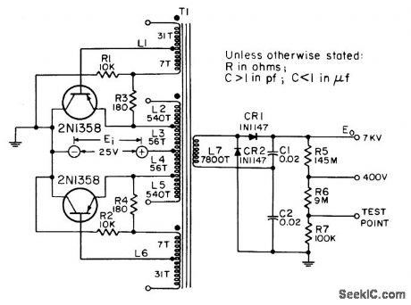
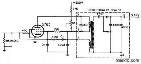
Provides high-voltage source for screen grid and final anode of 5 to 12-inch magnetic-deflection cathode-ray tubes in equipment having full or partial transistorization. Full-wave d-c to d-c converter, with transistor load connected between voltage source and emitter, permits attaching collectors to grounded or chassis-connected heat sink.-NBS, Handbook Preferred Circuits Navy Aeronautical Electronic Equipment, Vol. II, Semiconductor Device Circuits, PSC 6 (originally PC 202), p 6-2. (View)
View full Circuit Diagram | Comments | Reading(804)
PHOTOMULTIPILIER_SUPPLY
Published:2009/7/21 4:46:00 Author:Jessie
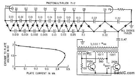
String of Cockcroft-Walton voltage doublers multiplies a-c output voltage of blocking oscillator to step up battery voltage to required 2 kv. Regulation is reasonably constant up to 0.4 ma plate current. –R. P. Rufer, Battery Powered Converter Runs Multiplier Phototube, Electronics, 33:28, p 51. (View)
View full Circuit Diagram | Comments | Reading(790)
Digital_tare_compensation
Published:2009/7/25 5:41:00 Author:Jessie
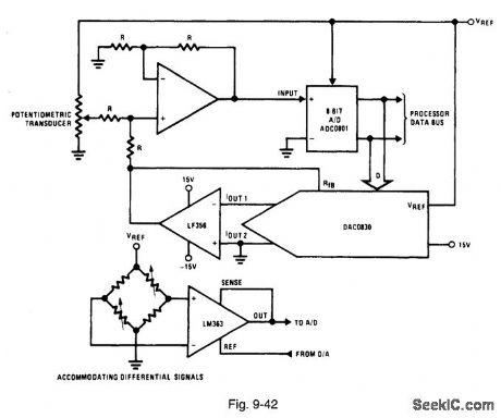
Figure 9-42 shows a DAC0830 and an ADC0801 connected to provide digital tare compensation. Such a function is used in a weighing system in which the weight of the scale platform, and possibly a container, is subtracted automatically from the total weight being measured. This expands the range of weight that can be measured by preventing a premature full-scale reading and allows an automatic indication of the actual unknown quantity. The DAC is initially given a zero code, and the system input is set to a reference quantity. A conversion of the input is performed, then the corresponding code is applied to the DAC. The DAC output is then equal to and of opposite polarity to the input voltage. This forces the amplifier output, and the ADC input, to zero. (In this case, an 8-bit ADC is used.) The DAC output is held constant so that any subsequent ADC conversion will yield a value relative in magnitude to the initial reference quantity. To ensure that the output code from the ADC generates the correct DAC output voltage, the two devices should be driven from the same reference voltage. For differential input signals, an instrumentation amplifier (such as an LM363) can be used. The output reference pin of the LM363 can be driven directly by the DAC, as shown. This will offset the ADC input. NATIONAL SEMICONDUCTOR, APPLICATION NOTE 271, 1994, P. 670. (View)
View full Circuit Diagram | Comments | Reading(1668)
Auto Parallel Charger Circuit
Published:2011/8/1 6:14:00 Author:Zoey | Keyword: Auto Parallel, Charger Circuit

T2, T4, T6, T8 and the relevant accessories constitute a constant circuit, the charge current is 50mA and 120mA.As soon as swtich K is closed, the charge current will turn to be 50mA; and if K is disconnected, the charge current will turn to be 120mA. Triode T1, T3, T5 and T7 and the rellevant accessories constitute a detection citcuit that is in a charge state. Potentiometer W is used to set to charge voltage. When it is fully charged, the battery will turn into a trickle maintain state. Trickle is set about 9mA by the resistances R4, R7,R10 and R13. (View)
View full Circuit Diagram | Comments | Reading(1038)
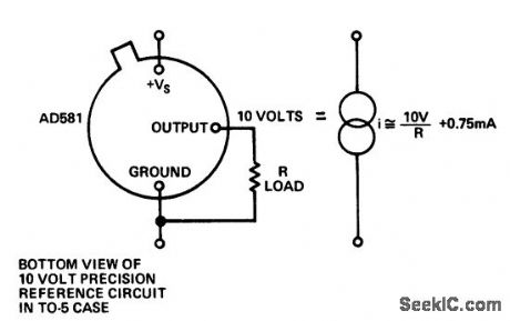
Two_terminal__10_volt_reference
Published:2009/7/20 20:53:00 Author:Jessie
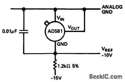
Two-terminal -10 volt reference (courtesy Analog Devices, Inc.). (View)
View full Circuit Diagram | Comments | Reading(533)
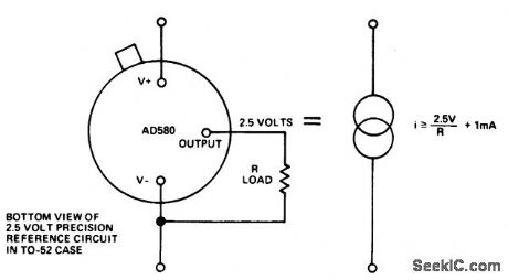
Two_component_precision_current_limiter
Published:2009/7/20 20:52:00 Author:Jessie
Two-component precision current limiter (courtesy Analog Devices, Inc.). (View)
View full Circuit Diagram | Comments | Reading(533)
Negative_voltage_regulators_for_5_6_12_or_15_volts_using_the_ECG9XX_series
Published:2009/7/20 20:52:00 Author:Jessie
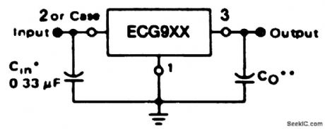
Negative voltage regulators for 5, 6, 12, or 15 volts using the ECG9XX series. Ratings for the three-terminal ECG9XX negative voltage regulators are as follows: ECG961, 5 volts; ECG963, 6 volts; ECG967, 12 volts; ECG969, 15 volts. A common is required between the input and output voltages. The input must remain 2 volts more negative than the output even during the high point on the input ripple voltage. These devices will handle up to 1 ampere without any heat sink. The input capacitor should be 0.33 μF if a tantalum or Mylar type is used. If an aluminum capacitor is used it should be 1.0 μF or larger (courtesy GTE Sylvania Incorporated). (View)
View full Circuit Diagram | Comments | Reading(691)
Negative_switching_regulator_15_volts_using_an_ECG915_or_ECG915D_IC
Published:2009/7/20 20:50:00 Author:Jessie
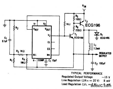
Negative switching regulator (15 volts) using an ECG915 or ECG915D IC. For a ±5% fixed output R1 is 3.65 ohms and R2 is 11.5 ohms. in metal can applications where Vz is required, connect a 6.2-volt zener in series with the regulated output.L1 is forty turns of AWG #20 enameled copper wire wound on Ferroxcube P36/22-387 pot core or equivalent with 0.009-inch air gap (courtesy GTE Sylvania Incorporated). (View)
View full Circuit Diagram | Comments | Reading(598)
Positive_switching_regulator5_volts_using_an_ECG915_or_ECG915D
Published:2009/7/20 20:49:00 Author:Jessie
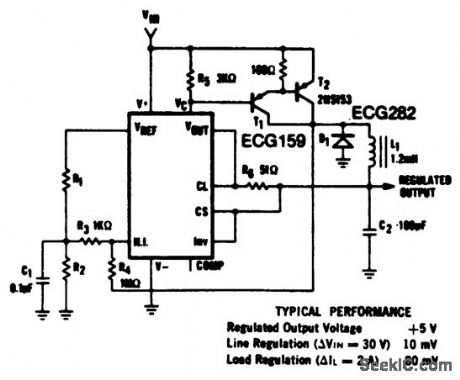
Positive switching regulator(5 volts) using an ECG915 or ECG915D. For a ±5% fixed output R1 is 1.15 ohms and R2 is 4.99 ohms. For metal can applications where Vz is required connect a 6.2-volt zener in series with the regulated output (courtesy GTE Sylvania Incorporated). (View)
View full Circuit Diagram | Comments | Reading(544)
Two_component_precision_current_limiter_1
Published:2009/7/20 21:03:00 Author:Jessie
Two-component precision current limiter (courtesy Analog Devices, Inc.). (View)
View full Circuit Diagram | Comments | Reading(496)
Precision_voltage_controlled_current_source_using_an_op_amp_and_two_FETs
Published:2009/7/20 21:00:00 Author:Jessie
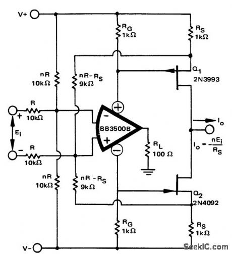
Precision voltage-controlled current source using an op amp and two FETs (courtesy Burr-Brown Research Corporation). (View)
View full Circuit Diagram | Comments | Reading(2023)
Adjustable_output_regulators_for_5_6_12_15_or_24_volts
Published:2009/7/20 20:59:00 Author:Jessie
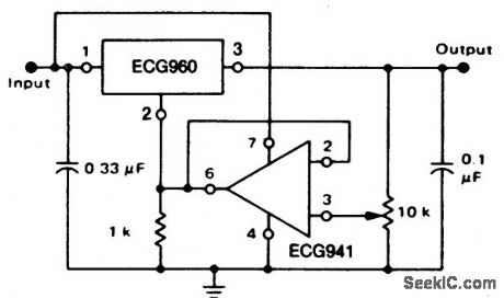
Adjustable output regulators for 5, 6, 12, 15, or 24 volts. The input capacitor is valued at 0.33 pF if Mylar or tantalum; if aluminum, it should be 1.0 pF or larger. Although the circuit shown is for a 7-volt output, voltages of 8, 14, 17, or 26 volts can be obtained by substituting ECG962, ECG966, ECG968 or ECG972, respectively, for the ECG960. These devices are three-terminal 1-ampere devices. The minimum voltage obtainable is 2 volts greater than the regulator voltage (courtesy GTE Sylvania Incorporated). (View)
View full Circuit Diagram | Comments | Reading(544)
Positive_floating_regulator_50_volts_using_an_ECG915_or_ECG915D_IC
Published:2009/7/20 21:09:00 Author:Jessie
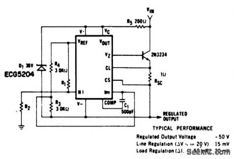
Positive floating regulator (50 volts) using an ECG915 or ECG915D IC. For a ±5% fixed output R1 is 3.57 ohms and R2 is 48.7 ohms. For metal can applications where Vz is required, an external 6.2-volt zener should be connected in series with the regulated output (courtesy GTE Sylvania Incorporated). (View)
View full Circuit Diagram | Comments | Reading(619)
Current_comparator_with_low_input_impedance_using_an_AD7570_10_bit_A_D_converter
Published:2009/7/20 21:09:00 Author:Jessie
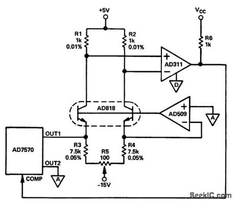
Current comparator with low input impedance using an AD7570 10-bit A/D converter (courtesy Analog Devices, Inc.). (View)
View full Circuit Diagram | Comments | Reading(593)
| Pages:127/291 At 20121122123124125126127128129130131132133134135136137138139140Under 20 |
Circuit Categories
power supply circuit
Amplifier Circuit
Basic Circuit
LED and Light Circuit
Sensor Circuit
Signal Processing
Electrical Equipment Circuit
Control Circuit
Remote Control Circuit
A/D-D/A Converter Circuit
Audio Circuit
Measuring and Test Circuit
Communication Circuit
Computer-Related Circuit
555 Circuit
Automotive Circuit
Repairing Circuit