power supply circuit
Digital_tare_compensation
Published:2009/7/25 5:41:00 Author:Jessie | From:SeekIC

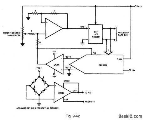
Figure 9-42 shows a DAC0830 and an ADC0801 connected to provide digital tare compensation. Such a function is used in a weighing system in which the weight of the scale platform, and possibly a container, is subtracted automatically from the total weight being measured. This expands the range of weight that can be measured by preventing a premature full-scale reading and allows an automatic indication of the actual unknown quantity. The DAC is initially given a zero code, and the system input is set to a reference quantity. A conversion of the input is performed, then the corresponding code is applied to the DAC. The DAC output is then equal to and of opposite polarity to the input voltage. This forces the amplifier output, and the ADC input, to zero. (In this case, an 8-bit ADC is used.) The DAC output is held constant so that any subsequent ADC conversion will yield a value relative in magnitude to the initial reference quantity. To ensure that the output code from the ADC generates the correct DAC output voltage, the two devices should be driven from the same reference voltage. For differential input signals, an instrumentation amplifier (such as an LM363) can be used. The output reference pin of the LM363 can be driven directly by the DAC, as shown. This will offset the ADC input. NATIONAL SEMICONDUCTOR, APPLICATION NOTE 271, 1994, P. 670.
Reprinted Url Of This Article:
http://www.seekic.com/circuit_diagram/Power_Supply_Circuit/Digital_tare_compensation.html
Print this Page | Comments | Reading(3)

Article Categories
power supply circuit
Amplifier Circuit
Basic Circuit
LED and Light Circuit
Sensor Circuit
Signal Processing
Electrical Equipment Circuit
Control Circuit
Remote Control Circuit
A/D-D/A Converter Circuit
Audio Circuit
Measuring and Test Circuit
Communication Circuit
Computer-Related Circuit
555 Circuit
Automotive Circuit
Repairing Circuit
Code: