power supply circuit
PREREGULATED_HIGH_VOLTAGE_SUPPLY
Published:2009/7/9 4:09:00 Author:May | From:SeekIC
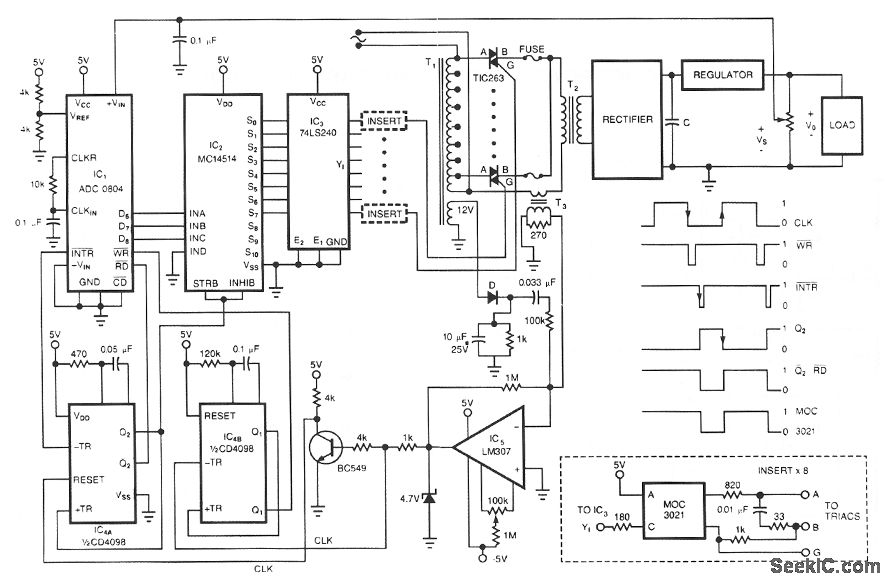
One of the control circuit's triacs selects the tap on main transformer T1, which provides the proper, preregulated voltage to the secondary regulator. T2 and its associated components comprise the second-ary regulator.The ADO 0804, IC1, digitizes a voltage-feedback signal from the secondary regulator's output. The MC1415 demultiplexer, IC2, decodes the digitizer's output. IC2, in turn, drives T1's optoisolated triacs via the 74LS240 driver chip, IC3, and associated optoisolators.Transformer T3 samples the circuit's current output. The auxiliary, 12 V winding on T1 ensures no-load starting. The combination of op amp IC5 and the inverting transistor, Q1, square this current signal. The output of Q1 is the CLK signal, which triggers one-half of the one shot, IC4A, to begin the circuit's A/D conversion. The one shots' periods are set to time out within 1/2 cycle of the ac input.Upon completion of its A/D conversion, IC1's INTR output triggers the other half of the one shot, IC4B, which enables the converter's data outputs. The rising edge of the CLK signal resets the one shot and latches the new conversion value into IC2. The latch, associated driver, and optoisolator trigger a selected triac according to the latest value of the voltage-feedback signal, VO.
Reprinted Url Of This Article:
http://www.seekic.com/circuit_diagram/Power_Supply_Circuit/PREREGULATED_HIGH_VOLTAGE_SUPPLY.html
Print this Page | Comments | Reading(3)

Article Categories
power supply circuit
Amplifier Circuit
Basic Circuit
LED and Light Circuit
Sensor Circuit
Signal Processing
Electrical Equipment Circuit
Control Circuit
Remote Control Circuit
A/D-D/A Converter Circuit
Audio Circuit
Measuring and Test Circuit
Communication Circuit
Computer-Related Circuit
555 Circuit
Automotive Circuit
Repairing Circuit
Code: