
Automotive Circuit
Index 83
The lighting and brake lamp circuit of Daewoo Racer
Published:2011/5/21 22:00:00 Author:Borg | Keyword: lighting and brake lamp, Daewoo Racer

2.brake signal lamp(see as 6)The brake signal lamps (El5~E18) are under the control of brake switch (S7). If there is a A/T device, then it is the cutting/closing switch(S3) that take control, when the brake signal lamps are lighting, the magnetic valve(Y4) coil of the fluid torque converter is cut off simultaneously, then the power transmission is halted.
(View)
View full Circuit Diagram | Comments | Reading(603)
The rear window defroster, wiper and washer circuit of Daewoo Racer
Published:2011/5/21 21:12:00 Author:Borg | Keyword: rear window defroster, wiper/washer, Daewoo Racer
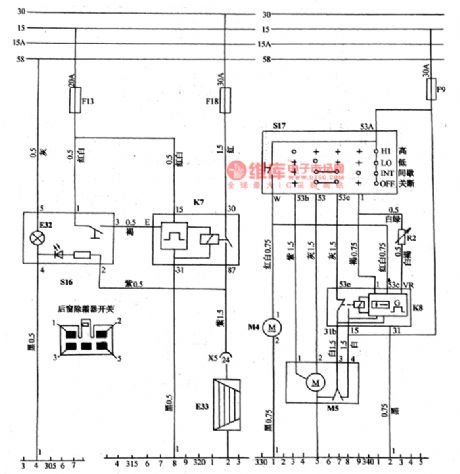
(7)wiper/washer system (see as Figure 10) When it is at the low speed gear(LO), the 53A-53 contact of wiper switch S17 is on, and the speed of the wiper arms is 30~45 times/min. When it is at the high speed gear (HI), the 53A-53b contact of the switch S17 is on, and the speed of the wiper arm is 60~70 times/min. When it is at the interval gear(INT), the 53A-I of the switch S17 is on, an 53-53e is also on, the interval relay (K8) takes action to cut off the normally closed contact(53e-53b), and the normally open contact (53e-15)is on, then the wiper motor(M5) is working at 1 gear, it wipes back and forth once and keep still for 4-21s, the interval time can be regulated by the control switch of R2.
(View)
View full Circuit Diagram | Comments | Reading(1002)
The electric window circuit of Daewoo Racer
Published:2011/5/21 20:55:00 Author:Borg | Keyword: electric window, Daewoo Racer

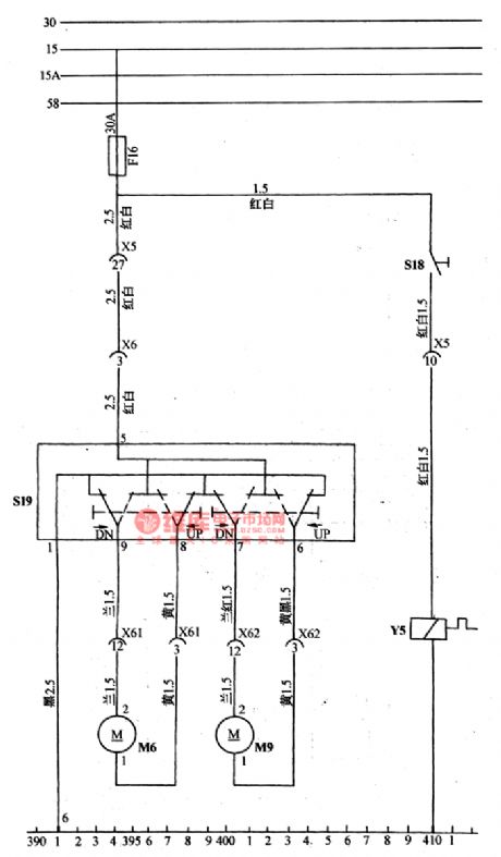
(9) the electric glass elevator(see as Figure 11a and 11b)It is a elevating motor which controls all the glass window by the combination switch of S19, the combination switch forms a circuit by 4 lever switches, the it can engage power brake and it links with the ground connection.
(View)
View full Circuit Diagram | Comments | Reading(1282)
The central door lock, radio and antenna circuit of Daewoo Racer
Published:2011/5/21 3:38:00 Author:Borg | Keyword: central door lock, Daewoo Racer
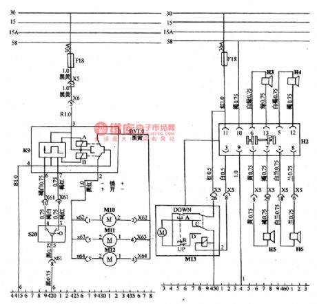
The central control door lock is controlled by keys(from outside) or handle(from inside) cf the driver door lock. When it is at the unlock position, the relay A closes. And the head-left, head-right,rear-left and rear-right door lock motors of M10,M11 and M12 rotate right at the same time, then the four doors open simultaneously. When S20 is at the lock position, the relay B closes , and the four motors rotate reversely, then the 4 doors are locked, so that it avoids the trouble of opening door one by one.
(View)
View full Circuit Diagram | Comments | Reading(1623)
The igniting circuit of Daewoo
Published:2011/5/21 3:50:00 Author:Borg | Keyword: igniting circuit
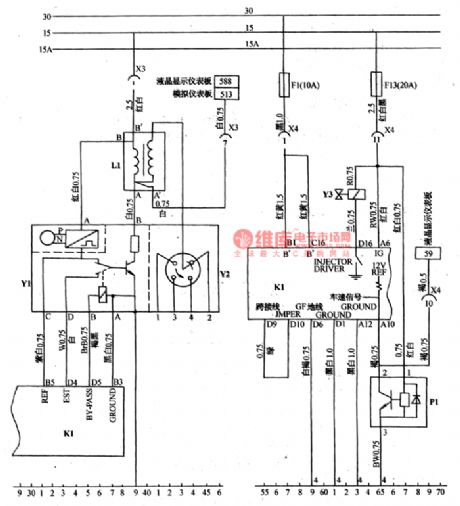
The igniting signal generator, igniting module Y1 and high voltage distributor compose into an integration. The resistance of the signal coil is 500~1500Ω, and the insulating resistance is infinitely large, the elementary - terminal connects with rotating speed meter.The elementary resistance ranges 0.25~0.45Ω, the secondary is 7.5~9.5KΩ, insulating resistance is infinite. The igniting sequence is 1-3-4-2, the points of testing electricity distributor is shown as Figure 2.
(View)
View full Circuit Diagram | Comments | Reading(669)
The fuse connection and control circuit of Daewoo Racer
Published:2011/5/21 20:45:00 Author:Borg | Keyword: fuse connection, control circuit, Daewoo Racer
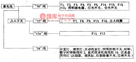
Figure 1b the relationship between each mainstream and the battery, igniting switch of Daewoo RacerThe igniting switch of S1 divides the car circuit into several mainstreams(see as Figure 1b and 1c): No.30 circuit links with the fire wire of the battery positive point; No.15 circuit, when the igniting switch is ON or ST , the fire wire is conducting, when it is OFF , the fire wire is not conducting; No.15 circuit is conducting when the igniting switch is ON , but not conducting when the switch is ST ; No.30 is passable only when the igniting switch is ST . (View)
View full Circuit Diagram | Comments | Reading(633)
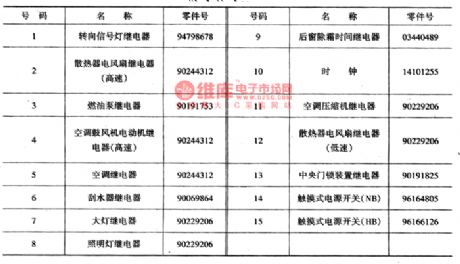
The positions of the relay and fuse on the central connection box of Daewoo Racer
Published:2011/5/22 0:34:00 Author:Borg | Keyword: central connection box, Daewoo Racer
There are two types of car bodies of Daewoo: the concave and the convex. The car equipment weighs 935kg(hand transmission) or 965kg(auto transmission), and the permitted weights are 1420kg and 1435kg. The max speeds are 165kg and 157kg. The model of the engine is Cl5CFOHC, and the engine is a 4-cylinder in-line water cooling throttle injection(single jet) engine, the diameter is 76.5mm, piston stroke is 8105mm, emission is 1498ml, compression ratio is 9.0, max power is 65.44kW/5500rpm, the maximum torque is 126.4N.m/30Orpm, it started by e-ignition, igniting advance angle is 10°(idling speed is 700±5Orpm).
(View)
View full Circuit Diagram | Comments | Reading(1549)
The power supply and starter circuit of Daewoo Racer
Published:2011/5/22 0:14:00 Author:Borg | Keyword: power supply, Daewoo Racer

Figure 1c The power supply and staring circuit of Daewoo RacerG1-battery; G2-AC generator; M1-starter; S1-igniting switch; S2-neutral gear switch; F1(10A):the ECM terminals(B1,C16) of generator e-controller; F2(10A):the width lamp and instrument lamp linked by No.58 circuit; F3(10A):the head high beam(left); F4(10A):the head high beam(right). High beam indicator.F5(10A):the head low beam(left); F6(10A):the head low beam(right); F14(30A):the fan relay of radiator(high speed and low speed). (View)
View full Circuit Diagram | Comments | Reading(1277)
Multivibrator circuit
Published:2011/5/23 20:49:00 Author:John | Keyword: Multivibrator
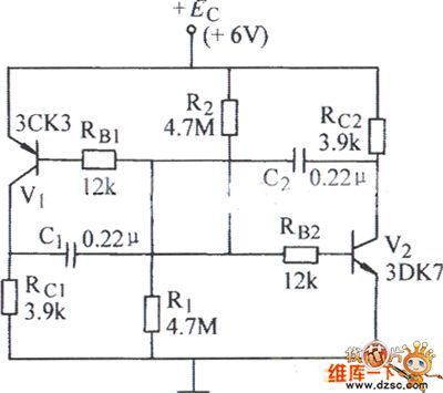
Multivibrator circuit is shown below.
(View)
View full Circuit Diagram | Comments | Reading(541)
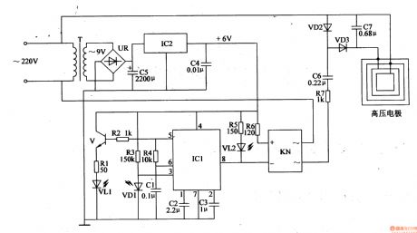
Electronic Bird Repeller (2)
Published:2011/5/20 5:13:00 Author:Sue | Keyword: Electronic, Bird, Repeller
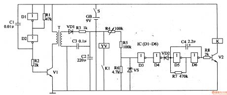
When S is on, multivibrator generates signals. T generates 300V voltage and charges C2. When D3's voltage reaches 4.5V, D4's output has high level, making VD2 disconnected. Low frequency oscillator stops working. V2 is connected and YV is connected. The gong is knocked to make a sound.
When YV works, C2's voltage is used and C3's voltage is higher than 4.5V. D4's output has low level and VD2 is connected. V2 is disconnected, K and YV are released and C2 begins to charge. There will be anautomatic knock at the gang. (View)
View full Circuit Diagram | Comments | Reading(1286)
Electronic Bird Repeller (1)
Published:2011/5/20 5:06:00 Author:Sue | Keyword: Electronic, Bird, Repeller
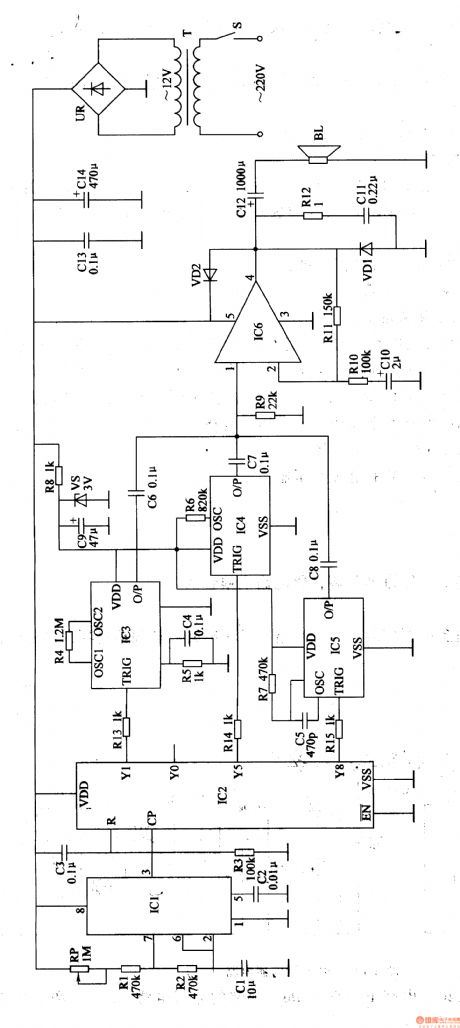
When S is on, 220V voltage will provide IC1,IC2,IC6,IC3,IC5 with working voltage.After the clockpulse generator begins to oscillate, IC2 will count the input pulse.
When the first pulse comes, Y1 outputs high level, and IC3 begins to work. O/P will output firecracker sound signals. BL will make a sound of firecracker.
When the 5th pulse comes, Y5 outputs high level, and IC4 begins towork. O/P will output sound signals and BL will make a sound of Di di, be careful .
When the 8th pulse comes, Y8 outputs high level, and IC5 begins to work. O/P will output bark signals and BL will make a barking sound.
When the 11th pulse comes, Y1 outputs high level again, BL makes a sound of firecracker. The circuit works in this order to drive birds away. (View)
View full Circuit Diagram | Comments | Reading(1716)
Electronic Pest Repeller (1)
Published:2011/5/19 3:02:00 Author:Sue | Keyword: Electronic, Pest Repeller

As seen in figure 4-178, the electronic pest repeller circuit consists of power circuit and multivibrator circuit.
When the power is on, an ac voltage of 220V will generate 12V direct voltage after the reduction, rectification and filtering by T, VD1-VD4 and C1. The 12V voltage will be sent to IC.
After the multivibrator begins to work, IC's 3 pin will output square form wave with a frequency of 48kHz, which will be transformed to ultrasonic wave by BL. The ultrasonic wavewill beemitted and can repel the pests.
When R1,R2's resistance value or C2's capacity are changed, the working frequency of the multivibrator can be changed.
(View)
View full Circuit Diagram | Comments | Reading(1777)
Electronic Bird Repeller (5)
Published:2011/5/20 5:33:00 Author:Sue | Keyword: Electronic, Bird, Repeller

In the daytime, IC1's inside switch is on and A will oscillate, outputting low frequency oscillator signals. When IC2's 3 pin outputs high level, K1 is connected. IC2's 2 pin will output 6 V voltage which will provide driving circuit with working voltage. The other circuit will provide IC3 with 3V working voltage. When IC2's 3 pin outputs low level, IC3-IC5 stops working.
When IC3 begins to work, O/P outputs signals, and BL makes a sound of fire cracker.
In the evening, VD1 is disconnected and the circuit doesn't work. (View)
View full Circuit Diagram | Comments | Reading(3977)
Electronic Bird Repeller (4)
Published:2011/5/20 5:27:00 Author:Sue | Keyword: Electronic, Bird, Repeller

When S is on, the square form wave generator begins to work and outputs square form pulse signal with an adjustable duty ratio. When the pulse delays upgoing, VF1 is connected. The audio signals it generates will drive BL to make a DU sound. When the pulse delays downgoing, VF1 is disconnected and the multivibrator stops working. In this circumstances, the multivibrator and the audio driving circuit works intermittently under the control of the signals and power circuit. (View)
View full Circuit Diagram | Comments | Reading(2380)
Electronic Bird Repeller (3)
Published:2011/5/20 5:22:00 Author:Sue | Keyword: Electronic, Bird, Repeller
When there is bird, VT is disconnected,Kdoesn't work and BL makes no sound.
When there is bird, BM will transform the bird singing into electric signal, which will be sent to VT and make VT connected after the signal is amplified. K is connected and BL makes a sound of firecracker. When K is connected, C6 discharges until K is released. Then K2 is disconnected, sound circuit and audio amplifier will stop working. BL stops making a sound. (View)
View full Circuit Diagram | Comments | Reading(585)
Biochemical Incubator Controller
Published:2011/5/16 5:00:00 Author:Sue | Keyword: Biochemical, Incubator, Controller
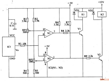
When the temperature is within the proper range, IC2's 2 pin's voltage is higher than that of 5 pin. 3 pin, 6 pin and 2 pin have the same voltage. 1 pin and 7 pin output low level, and k1, k2 are not connected. The cooling and heating circuits don't work.
When the temperature is higher than the set highest temperature, IC2's 3 pin's and 6 pin's voltage will be higher than that of 2 pin and 5 pin. IC2's 1 pin will have a high level instead of low level, making V2 connected and K2 connected. Its normally open contactor is connected, making the cooling system begin to work. When the temperature is lower than the set lowest temperature, IC2's 3 pin and 6 pin will have a lower voltage than 2 pin and 5 pin. IC2's 7 pin will have a high level,making V1 connected, and its normally open contactor is connected, making the heating circuit begin to work. (View)
View full Circuit Diagram | Comments | Reading(1074)
Soil Moisture Tester
Published:2011/5/14 3:37:00 Author:Sue | Keyword: Soil Moisture, Tester
Working Principle:
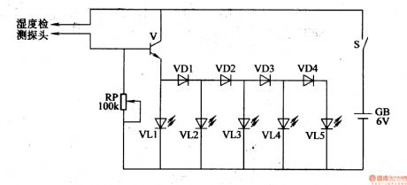
As seen in the figure 4-210,the soil moisture tester circuit consists of moisture detecting head, transistor V, diode VD1-VD4, LED VL1-VL5, potentiometer RP, power switch S and battery GB.
When the soil is too dry, V and VD1-VD4 are disconnected. VL1-VL5 then are not illuminated. When the soil deteced are moist, the water in the soil will make the resistance value between the 2 elektrodes of the detecting head become small, so V is connected and VL1-VL5 are illuminated one by one. The moister the soil is, the stronger breakover ability V will have, so the illuminated LED will be more. (View)
View full Circuit Diagram | Comments | Reading(2339)
Inverter (1)
Published:2011/5/16 3:24:00 Author:Sue | Keyword: Inverter
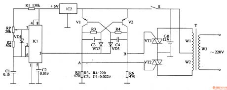
When S is connected, storage battery GB will provide monostable trigger circuit with a voltage of +12V, and another circuit will provide nonstable multivibrator circuit with +6V which is stablized by IC2.
When nonstable multivibrator begins to work, IC1's 3 pin will output oscillate pulse signal with a frequency of 100Hz, making V1 and V2 connected in turn. A and B will output high level flat pulse in turn, making VT1 and VT2 begin to work alternately, which can generate an alternating voltage of 5OHz、220V on T's secondary winding. (View)
View full Circuit Diagram | Comments | Reading(587)
Electronic Mouse Killer (6)
Published:2011/5/16 3:46:00 Author:Sue | Keyword: Electronic, Mouse Killer
IC's 5 pin can output oscillator signal, which will drive VL1 to generate modulated infrared ray after the signal is amplified by V. When there is no mouse, VD1 receives no infrared ray, and IC1 will oscillate automatically, making 8 pin output high level. VL2 is not illuminated and KN and high voltage circuit don't work.
When there is mouse in the infrare ray detecting area, VD1 will receive the reflected infrared ray and turn 8 pin's high level into low level. VL2 is illuminatedand KN begins to work. High voltage will kill the mouse. When the mouse dies, the power is cut off, making VD1 stop working. IC1's 3 pin has no input signal, and 8 pin has high level. VL2 is not illuminated and the whole circuit stops working. (View)
View full Circuit Diagram | Comments | Reading(2484)
Electronic Mouse Killer (4)
Published:2011/5/16 4:37:00 Author:Sue | Keyword: Electronic, Mouse Killer

When S is connected, 220V alternating voltage will generate 2KV high voltage,which will be sent to T's winding W2 after it is limited and changed by EL and T, and then the voltage will be sent to the high voltage electronic net through K. W3 will generate 3.5V alternating voltage, when HL is illuminated, the voltage can provide IC with working voltage after VD1-VD4's rectification and C1's filtering.
When the mouse touches the net, the high voltage current will kill the mouse. At the same time, K is connected, making IC begin to work and BL make a music warning sound, informing the users of the dead mouse. (View)
View full Circuit Diagram | Comments | Reading(1808)
| Pages:83/164 At 2081828384858687888990919293949596979899100Under 20 |
Circuit Categories
power supply circuit
Amplifier Circuit
Basic Circuit
LED and Light Circuit
Sensor Circuit
Signal Processing
Electrical Equipment Circuit
Control Circuit
Remote Control Circuit
A/D-D/A Converter Circuit
Audio Circuit
Measuring and Test Circuit
Communication Circuit
Computer-Related Circuit
555 Circuit
Automotive Circuit
Repairing Circuit