
Automotive Circuit
Index 85
The cruise control circuit of Buick-Century
Published:2011/5/18 0:04:00 Author:Borg | Keyword: cruise control, Buick-Century
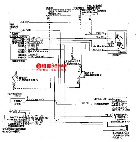
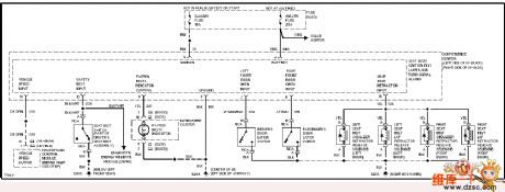
Car cruise control system can automatically keep a certain speed according to the driver's request without the driver pressing the plate, which can release the driver from tiredness and improve the comfort. In spite of the wind or the angle of the road, the car speed can be kept the same, which can reduce the oil consumption and the exhaust emission. The system consists of control switch, speed sensor and cruise control ECU, etc.
(View)
View full Circuit Diagram | Comments | Reading(519)
The idling speed detection and basic parameter setting circuit of Santana 2000GLi
Published:2011/5/16 7:58:00 Author:Borg | Keyword: idling speed, basic parameter, Santana

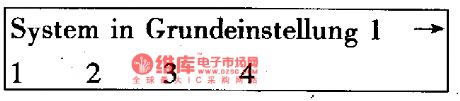

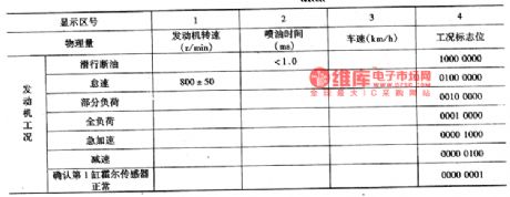
Idling speed is an operating mode of the engine, it's also useful for other operating mode detection if we exactly detect the main idling speed parameters, such as igniting angle of advance, the revolutions of the engine, the content of carbon monoxide and oil throughput.Before detection was taken, the engine coolant temperature should be no less than 80℃ , and the power supply voltage of the computer control should be higher than 12.2V, air-conditioning and other electrical equipment should be turned off, ventilation system should be without leakage, throttle is normal and the front wheels point to the head.The idling speed standard values of AFE engine are as follows.
(View)
View full Circuit Diagram | Comments | Reading(399)
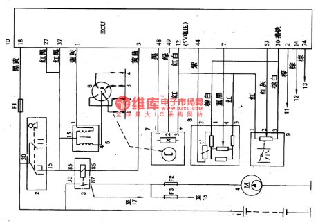
The fault detection circuit of Daewoo ESPERO air-conditioner compressor control
Published:2011/5/16 21:41:00 Author:Borg | Keyword: fault detection circuit, Daewoo ESPERO, air-conditioner

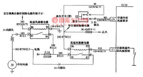
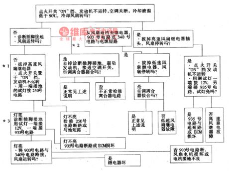
To make sure that engine will run stable when air-conditioner is work at the idling speed, and to lighten the load of the engine when accelerating(the throttle is open), the air-conditioning circuit is cut off. Daewoo ESPERO is installed with computer ECM control air-conditioner compressor and electric fans of condensers(see as Figure 26 and Figure 7).
This circuit consists of low-voltage switch, high-switch, air-conditioner power supply relay, air-conditioner clutch and compressor electromagnetic clutch.
The detection course of cooling fan control circuit is as follows:
(View)
View full Circuit Diagram | Comments | Reading(1455)
The parking and neutral gear switch circuit fault detection circuit of Daewoo ESPERO
Published:2011/5/16 21:57:00 Author:Borg | Keyword: parking gear, neutral gear, detection circuit
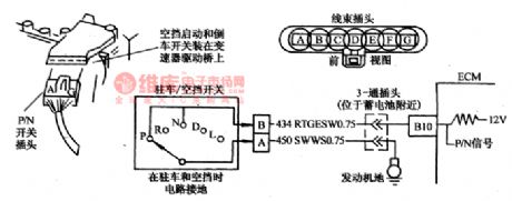
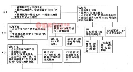
Parking/neutral(P/N) gear switch touch spot is part of the neutral staring switch, which is fixed in auto transmission drive bridge. When the car is at neutral gear(N) or parking(P) gear, the touch spot is closed; when the car is at geared state(R,D,L), the switch is cut off(see as Figure 25). The computer ECM imposes a igniting switch voltage on No.434 line through a current-limiting resistance, when voltage on the line is lower than 1V, then ECM will decide the switch is closed.
(View)
View full Circuit Diagram | Comments | Reading(820)
Millivoltmeter circuit
Published:2011/5/18 19:28:00 Author:John | Keyword: Millivoltmeter

Millivoltmeter circuit is shown below.
(View)
View full Circuit Diagram | Comments | Reading(2076)
Digital voltmeter circuit
Published:2011/5/18 19:30:00 Author:John | Keyword: Digital voltmeter
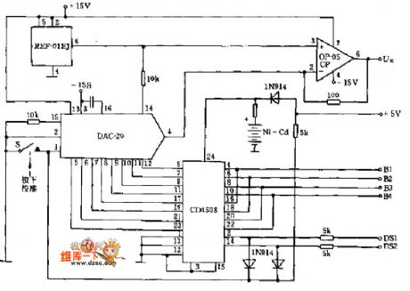
Digital voltmeter circuit is shown below.
(View)
View full Circuit Diagram | Comments | Reading(8)
Alternating Current Contactor Energy-Saving Circuit
Published:2011/5/17 5:48:00 Author:Sue | Keyword: Alternating Current, Contactor, Energy-Saving
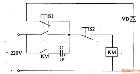
When the power is connected and S1 is pushed, 220V voltage will be sent to AC contactor KM’s coil, and make KM connected. Then C begins to charge. When S1 is released, C’s charging current makes KM remain connected, and VD will be connected to KM by S1 S2. Then the alternating current power will charge C in positive half period while discharge C in negative half period. KM will remain connected. (View)
View full Circuit Diagram | Comments | Reading(598)
The fault code of 33 detection circuit of Daewoo ESPERO
Published:2011/5/17 4:34:00 Author:Borg | Keyword: fault code, Daewoo
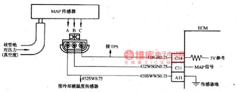
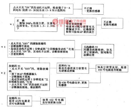
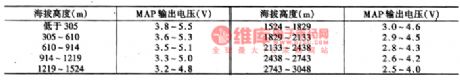
The fault code of 33 means that the signal voltage of manifold absolute pressure(MAP) sensor circuit is high and degree of vacuum is low. Manifold absolute pressure(MAP) sensor responds to the change of the pressure(vacuum drgree). When the igniting switch is at ON gear and the engine is still, the manifold pressure is larger than the atmospheric pressure, signal voltage is high, the ECM will use the signal as the parameter of car altitude and atmosphere pressure. When the engine is at idling speed, the MAP signal voltage values are as shown in Figure 20 and Figure 4.
MAP sensor check of admission manifold is shown as follows.
(View)
View full Circuit Diagram | Comments | Reading(1295)
AY915lB-the integrated circuit of microcomputer dialing
Published:2011/5/17 5:50:00 Author:Borg | Keyword: integrated circuit, microcomputer dialing
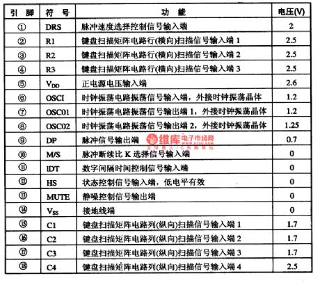
AY915lB is an integrated circuit of microcomputer dialing, which is widely used in communication and phone circuits.1function featuresAY915lB contains pulse dialing process circuits, silence-noise control circuits, key switch encoding circuits and other function circuits.2.pin functions and dataAY9151B is in 18-lead dual in-line package, whose pin functions and data are listed in Table 1.Table 1 pin functions and data of AY9151B
(View)
View full Circuit Diagram | Comments | Reading(441)
The fault code of 21 detection circuit of Daewoo ESPERO
Published:2011/5/17 6:16:00 Author:Borg | Keyword: fault code, detection circuit
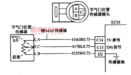

The fault code of 21 means that the signal voltage of throttle sensor is too high. TPS offers a signal that changes with throttle position, and the normal signal voltage is lower than 1.25v when at idling speed, and the voltage about 4.5V when the throttle is open. TPS is one of the most important input parameters, which is used to control the oil volume and other outputs by ECM. When the throttle is closed, the voltage should be lower than 1.25v, as the throttle is getting wide open, TPS voltage will raise up gradually.
(View)
View full Circuit Diagram | Comments | Reading(721)
The fault code of 24 detection circuit of Daewoo ESPERO
Published:2011/5/17 2:53:00 Author:Borg | Keyword: fault code, detection circuit, Daewoo ESPERO
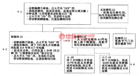
*1. This step is to check whether fault code 22 is actual or interrupted fault. The conditions of fault 22 are: the engine is running; TPS voltage is lower than 0.16V(160mV).*2.this step is to imitate the phenomena of fault code 22(see the cause of it), if it is flashing, then it means that ECM and its circuit are normal.*3. This step is check if the reference voltage of TPS send by ECM and sensor ground connection are good.*4. If No.416 circuit(V REF is 5v) is broken, ECM will save fault code of 34, too. (View)
View full Circuit Diagram | Comments | Reading(469)
The detection circuit on running engine of Santana 20OOGLi
Published:2011/5/16 4:14:00 Author:Borg | Keyword: detection circuit, Santana


(1)Input the function code of 0l at idling speed after connecting V.A.Gl551 fault detecter, then choose engine electric sprayer control detection gear , the words fast-speed data delivering, assisting function selection xx will come out on the screen, i.e
(2)Input function code of 08(read testing data), press Q key to confirm, then the words read the testing data, assisting to input the team No. , i.e
Since this is to judge if the engine computer can tell the different conditions, so input the code of 04 and press the key of Q to confirm, then the data on team 04 will be shown on the screen.
(View)
View full Circuit Diagram | Comments | Reading(461)
the square root circuit can be used in a variety of arithmetic circuit
Published:2011/5/12 22:48:00 Author:Fiona | Keyword: the square root circuit
Circuit function
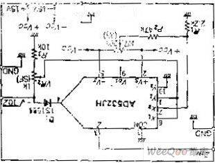
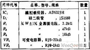
Square root circuit is used as a part of the true RMS conversionin and vector operations loop in the analog computing circuit, it can obtain the output voltage of EO =- √ 10 Z, the input voltage of Z 0 to positive and negative 10V, its output voltage is 0 -10V and 0 ~ 10V. Circuit Work When the circuit is used as multiplication IC,feedback the output to the X, Y input, then input signal from the Z input, so that the multiplication unit is equal with feedback circuit connected to the OP amplifier.
Diode D1 connected to the output is necessary to prevent saturating when the Z input voltage approaches 0. (View)
View full Circuit Diagram | Comments | Reading(457)
Inverter (2)
Published:2011/5/16 3:34:00 Author:Sue | Keyword: Inverter (2)

Working Principle:
When power switch S is connected, low frequency oscillator begins to work and generates 50Hz oscillator signals. After the signal is buffered and reshaped by NOT gate D3, it will be sent to VF2's grid electrode through R3, and the other circuit will be sent to VF1's grid electrode after it is backward processed by NOT gate D4. So VF1 will work during the oscillator signal's positive half period while VF2 will work during the signal's negative half period. Finally after the signal is push-pull amplified, it will generate a alternating voltage of 220V at the two terminal of T's secondary winding. (View)
View full Circuit Diagram | Comments | Reading(1363)
Buick Seat Backrest Adjustment Circuit
Published:2011/5/17 7:24:00 Author:Robert | Keyword: Buick, Seat, Backrest, Adjustment

The Buick Seat Backrest Adjustment Circuit is shown below.
(View)
View full Circuit Diagram | Comments | Reading(503)
Buick Passive Seat Safety System Circuit
Published:2011/5/17 7:13:00 Author:Robert | Keyword: Buick, Passive, Seat, Safety System
The Buick Passive Seat Safety System Circuit is shown below.
(View)
View full Circuit Diagram | Comments | Reading(399)
Buick Headlight Circuit (With DRL)
Published:2011/5/17 7:07:00 Author:Robert | Keyword: Buick, Headlight Circuit, DRL
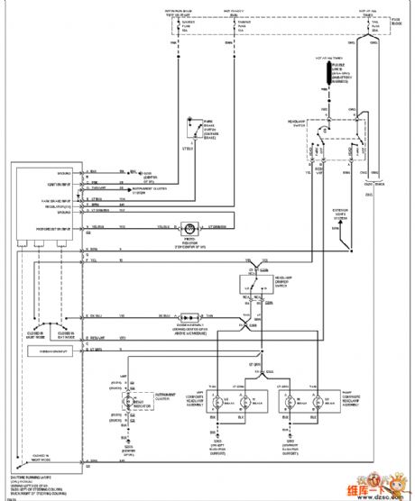
The Buick Headlight Circuit (With DRL) is shown below.
(View)
View full Circuit Diagram | Comments | Reading(487)
Buick Front Wiper And Washer Circuit
Published:2011/5/17 7:04:00 Author:Robert | Keyword: Buick, Front Wiper, Washer

The Buick Front Wiper And Washer Circuit is shown below.
(View)
View full Circuit Diagram | Comments | Reading(724)
Buick External Light Circuit (Car)
Published:2011/5/17 6:59:00 Author:Robert | Keyword: Buick, External Light
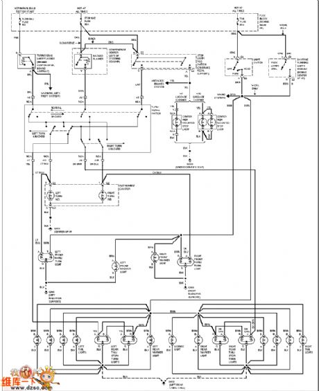
The Buick External Light Circuit (Car) is shown below.
(View)
View full Circuit Diagram | Comments | Reading(429)
Buick Automatical Door Lock Circuit
Published:2011/5/17 6:54:00 Author:Robert | Keyword: Buick, Automatical Door Lock
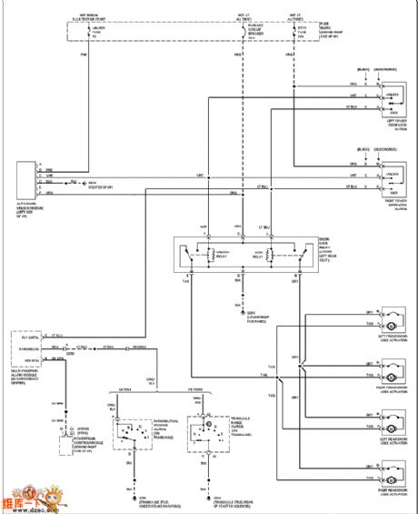
The Buick Automatical Door Lock Circuit is shown below.
(View)
View full Circuit Diagram | Comments | Reading(446)
| Pages:85/164 At 2081828384858687888990919293949596979899100Under 20 |
Circuit Categories
power supply circuit
Amplifier Circuit
Basic Circuit
LED and Light Circuit
Sensor Circuit
Signal Processing
Electrical Equipment Circuit
Control Circuit
Remote Control Circuit
A/D-D/A Converter Circuit
Audio Circuit
Measuring and Test Circuit
Communication Circuit
Computer-Related Circuit
555 Circuit
Automotive Circuit
Repairing Circuit