
Automotive Circuit
Index 84
Electronic Mouse Killer (2)
Published:2011/5/16 4:21:00 Author:Sue | Keyword: Electronic, Mouse Killer

Working Principle:
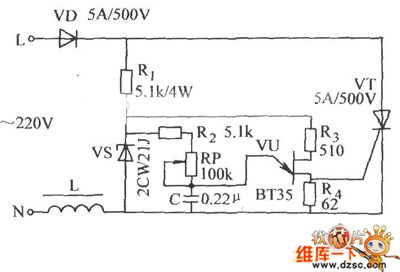
As seen in the figure 4-193,this mouse killer circuit is simple. It consists of 5 times voltage rectifying circuit and labyrinth type poles.
When the 220V alternating voltage is rectified by VD1-VD5 and C1-C5, it will generate 1.5kV pulse high voltage on labyrinth type poles. When the mouse steps on it, the current will go through the mouse and kill it.
Component choices:
R: 1/2 W metal film resistor.
C1-C5: Ceramic capacitor with a withstand voltage of 600V.
VD1-VD5: 1N4007 silicon rectifying diode. (View)
View full Circuit Diagram | Comments | Reading(5074)
Electronic Mouse Killer (1)
Published:2011/5/16 4:03:00 Author:Sue | Keyword: Electronic, Mouse Killer

When there is no mouse, IC1's output terminal will output high level. V1, high frequency oscillator, sound alarm circuit and high-voltage generator all don't work. When there is a mouse in the certain area, IC1's infrared ray will be reflected by the mouse and then receivedand processed by IC1, making IC1's output terminal have low level. Then V1 is connected and high frequency oscillator begins to work. IC2's 3 pin will output high frequency pulse signal,. which will generate 5kV pulse high voltage and kill the mouse. At the same time, V1 triggers the alarm circuit, driving BL make a warning sound. (View)
View full Circuit Diagram | Comments | Reading(2680)
Electronic Mouse Exterminator (4)
Published:2011/5/17 5:38:00 Author:Sue | Keyword: Electronic, Mouse Exterminator
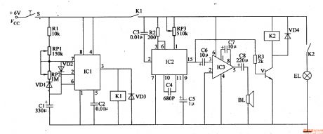
When S is connected, IC1’s 3 pin outputs high level, making the circuit begin to work. IC2’s 15 pin will output “meow” signal, which can drive BL to make a loud “meow” sound. Then V will work intermittently with the change of “meow” sound, and the bulbs will keep twinkling.
Then when IC1’s 6 pin’s voltage becomes higher than 2Vcc/3, IC1’s inside circuit reverses, making 3 pin have a low voltage, and K1 is released, which will stop the circuit. Then IC1’s 2 pin and 6 pin will have a lower voltage. When the voltage is lower than Vcc/3, K1 will be connected, and the circuit begins to work again. (View)
View full Circuit Diagram | Comments | Reading(624)
Electronic Mouse Exterminator (2)
Published:2011/5/17 5:22:00 Author:Sue | Keyword: Electronic, Mouse Exterminator
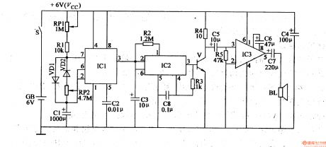
When S is connected, IC1’s 2 pin and 6 pin have low level, and its 3 pin outputs high level, making IC2 begin to output meow electronic signal, which can drive BL to make a loud “meow”. At the same time, C1’s voltage becomes higher and higher. When IC1’s 2 pin and 6 pin have a voltage higher than 2Vcc/3, IC1’s 3 pin’s high level turns into low level, and BL stops the sound.
Then C1’s voltage becomes lower and lower. When the voltage reduces to Vcc/3, IC1’s 3 pin has a high level, driving BL to make a “meow” sound. (View)
View full Circuit Diagram | Comments | Reading(583)
Car Turing Alarm (LD7208 Specific IC) Application Circuit
Published:2011/5/22 1:24:00 Author:Robert | Keyword: Car, Turing, Alarm, Specific IC, Application
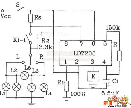
The Car Turing Alarm (LD7208 Specific IC) Application Circuit is shown in the picture below. This circuit's main functions are: when it is working normally and the car lamp is intact, the car lamp and the driver seat's monitoring lights would flash toghter and the flash frequency is 80 per minute. Once the car lamp is damaged, the monitoring light's flash frequency would speed up to double to alarm.
(View)
View full Circuit Diagram | Comments | Reading(475)
Complementary tube multivibrator circuit
Published:2011/5/23 20:11:00 Author:John | Keyword: Complementary tube multivibrator
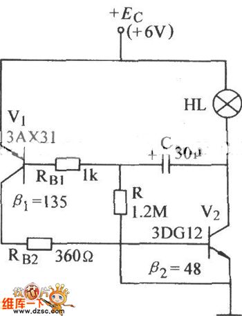
Complementary tube multivibrator circuit is shown below.
(View)
View full Circuit Diagram | Comments | Reading(623)
Electronic voltage vibration circuit
Published:2011/5/23 20:12:00 Author:John
Electronic voltage vibration circuit is shown below.
(View)
View full Circuit Diagram | Comments | Reading(577)
Electronic Pest Repeller (2)
Published:2011/5/19 3:09:00 Author:Sue | Keyword: Electronic, Pest Repeller
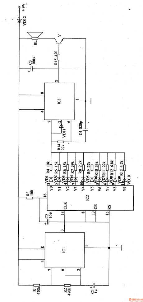
IC2 is a COMS decimal counter integrated circuit. It has 10 decoding output terminals(Y0-Y9). When it is working, its output terminals will output high level in turn. VD1-VD10 and R4-R13 will control IC3, generating 10 continuous frequency signals.
The audio output circuit consists of V and BL. IC3's 3 pin will output ultrasonic wave signal, which will emit ultrasonic wave through BL.
When the power is on, if BL can output audio signals with frequency that will change in every minute, then the circuit is working well. (View)
View full Circuit Diagram | Comments | Reading(796)
Electronic Mouse Exterminator (1)
Published:2011/5/17 5:13:00 Author:Sue | Keyword: Electronic, Mouse Exterminator (1)
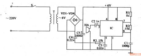
When S is connected, an alternating voltage of 220V will generate a direct current voltage of 6V after reduction, rectification and filtration. The 6V voltage will be sent to IC's 4 pin and 8 pin, making the oscillator begin to work.
The 50Hz alternating current signal of T will be sent to IC's 5 pin through C4, R3, controlling the oscillator. IC's 3 pin will output 20-40kHz varied sweep frequency signals, which will be sent to HA through C2, forcing HAto generate some sound pressure to drive the mouse away. (View)
View full Circuit Diagram | Comments | Reading(761)
Electronic Mouse Exterminator (3)
Published:2011/5/17 5:31:00 Author:Sue | Keyword: Electronic, Mouse Exterminator
When the power is connected, the astable multivibrator begins to work. IC1’s 7 pin will output 11Hz oscillator signal. After the signal is transformed into sawtooth wave by V, it will output 18-30kHz sweep frequency signal from IC2’s 4 pin after IC2’s control and process. The signal will force HA to emit ultrasonic beam of 100dB after TWH68’s amplification and boost. The ultrasonic beam can then drive awaymice or pests in a certain area. (View)
View full Circuit Diagram | Comments | Reading(420)
The ECM plug voltage circuit of Daewoo-ESPERO
Published:2011/5/18 22:45:00 Author:Borg | Keyword: ECM, voltage circuit, Daewoo-ESPERO
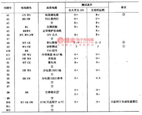
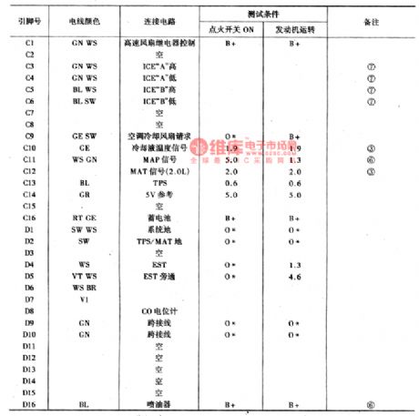
Before the test is done, there are some conditions to conform:①the engine reaches the normally working temperature; ② the test pin has not connected with the ground.Instructions of marked notes are shown in 13-4.B+: system voltage; *:voltage lower than 0.5v; ▽:voltage lower than 1v; ① the pulse voltage that changes with front drive wheel, it ranges from 0.6v to battery voltage; ②the voltage is 12V in the starting 2S; ③voltage changes with temperature; ⑤the system voltage when the transmission is at the heading or back-up gear; ⑥the changing voltage; ⑦the changing A.C voltage. (View)
View full Circuit Diagram | Comments | Reading(1049)
transformer oscillator circuit
Published:2011/5/19 19:36:00 Author:John | Keyword: transformer, oscillator
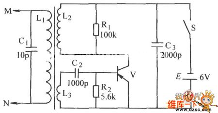
Transformer oscillator circuit is shown below.
(View)
View full Circuit Diagram | Comments | Reading(911)
The fault code diagram of Santana 2000GLi
Published:2011/5/16 4:27:00 Author:Borg | Keyword: fault code, Santana
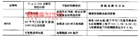
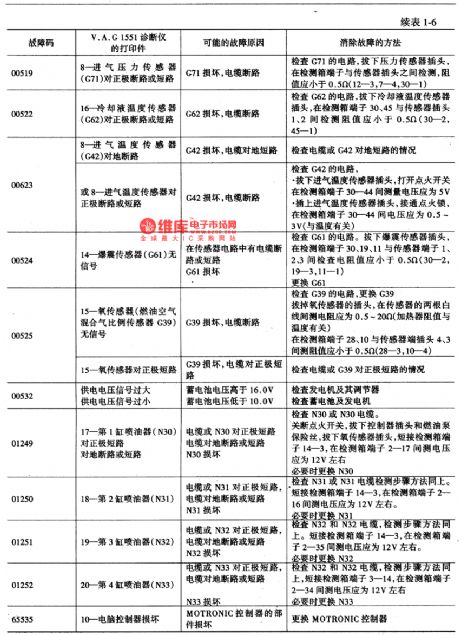
Fault codes are represented by 5 bit numbers. Before switching the shown faulted components, we should check if the wires and connected tightly, especially for sporadic faults(sp). The fault codes are listed in Table 1, in the table, detection box is corresponding to computer connecting terminals.
(View)
View full Circuit Diagram | Comments | Reading(523)
Agricultural Products Automatic Drying Case
Published:2011/5/17 6:07:00 Author:Sue | Keyword: Agricultural Products, Automatic, Drying Case

After the drying case begin to work, RS’s resistance value becomes smaller, and IC2’s 4 pin’s voltage becomes higher, making the oscillator begin to work. IC2’s 3 pin outputs high level, illuminating VL3, and M begins to drive the steam out of the case. When C4’s voltage reaches 6.7V, 3 pin outputs low level and M stops working. Then C4’s voltage becomes lower, illuminating VL3 again, and M begins to work. When the it is not too wet, IC’2 will stop working. When it is too wet, IC2 works again. So the circuit works like this until the product is dry and VL3 is not illuminated. (View)
View full Circuit Diagram | Comments | Reading(510)
The diagnosis circuit of Daewoo ESPERO fault code of 15
Published:2011/5/18 1:33:00 Author:Borg | Keyword: diagnosis circuit, Daewoo ESPERO
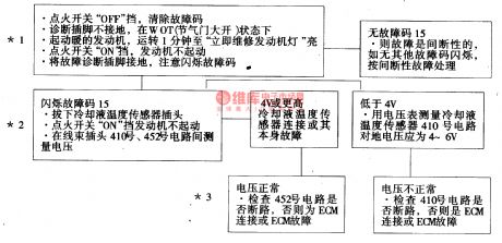
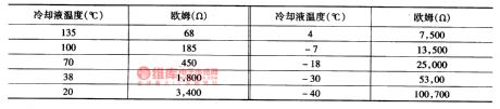
The code of 15 means that the signal voltage of coolant temperature sensor is high --indicating low temperature, whose change regulation of resistance and signal voltages is the same with the code of 14, and its influence range is also the same with the code of 14. Its circuit is shown in Figure 16 and Figure 4.
*1 is used to detect whether the fault is actual or caused by interrupted factors, the conditions of generating the fault is: the engine has run for more than 1min; the signal voltage indicates that the temperature of coolant is lower than -37℃, which is opposite to the code of 15 which means warm engine .
(View)
View full Circuit Diagram | Comments | Reading(638)
The transmission SIL circuit fault detection of Daewoo ESPERO
Published:2011/5/17 2:33:00 Author:Borg | Keyword: SIL, fault detection, Daewoo ESPERO
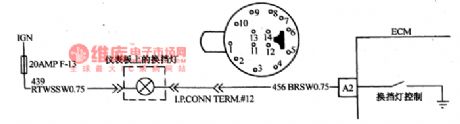
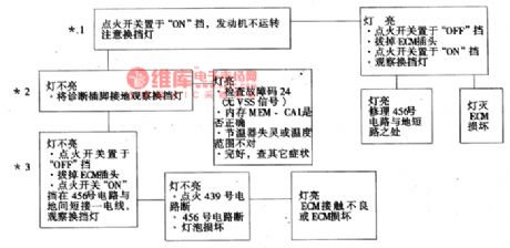
In the Daewoo ESPERO of hand transmission, SIL can remind the driver to shift the transmission to another gear according to the rotating speed and load of the engine and the car speed, by which the engine was made sure to consume the minimum oil. The shift indicator light is on the dashboard, which is lighted by the ECM driver.
*1.There the SIL should be off, if not, that means the No. 456 circuit is short or ECM is broken.*2.When the detection plug connects with the ground, ECM should connect No.456 with the earth and the SIL should light.
(View)
View full Circuit Diagram | Comments | Reading(686)
The fault code 51 and 54 detection circuit of Daewoo ESPERO
Published:2011/5/17 1:13:00 Author:Borg | Keyword: detection circuit, Daewoo ESPERO


The computer codes of 51 and 54 represent the potentiometer is malfunctioning, which is used to adjust the CO content in the emission. CO potentiometer is an adjustable resistance to control the delivering signal voltage to ECM. After the repairing, the CO content in the engine emission is supposed to be 0.3%~0.5% , in the normal condition, the D8 signal voltage on ECM plug should be 0.08~3.8V. The output signal of CO potentiometer is one of the signals that control the fuel injection, whose circuit connection are shown in Figure 28.
(View)
View full Circuit Diagram | Comments | Reading(1616)
The fault code of 34 diagnosis circuit of Daewoo ESPERO
Published:2011/5/18 0:06:00 Author:Borg | Keyword: fault code, detection circuit, Daewoo ESPERO
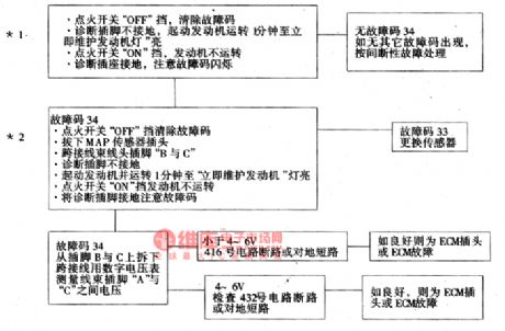
The fault code of 34 means that the signal voltage of manifold absolute pressure(MAP) sensor circuit is low and degree of vacuum is high, whose circuit condition is the same as fault 33.
*1. this is to make sure whether fault 34 is generated in the actual or interrupted condition, the generating conditions of fault 34 are: fault 21 has not been detected (the TPS signal voltage of throttle is high); the rotationl speed is less than 1200r/min; the reading of MAP signal voltage is less than 14kPa; the rotationl speed is more than 1200r/min; TPS is less than 20% (voltage is lower than 1V which is higher than that when throttle gate is closed).
(View)
View full Circuit Diagram | Comments | Reading(459)
The diagnosis circuit of fault code 24 of Daewoo ESPERO
Published:2011/5/18 0:05:00 Author:Borg | Keyword: fault code, detection circuit, Daewoo ESPERO
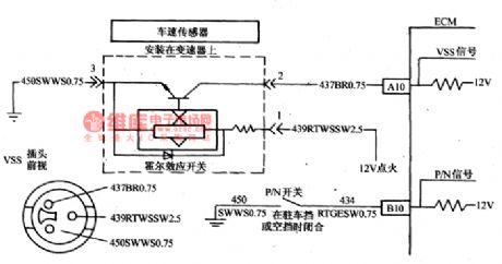
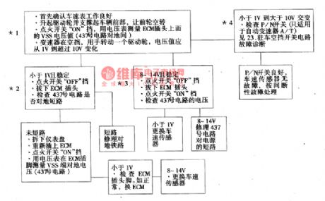
Computer ECM provides 12V voltage to speed sensor through the No. 437 circuit, and then the voltage goes back along the circuit. When the driven wheels run, the sensor makes the No.437 circuit connect the ground in turn, this pulse signals are generated 3683/1.6Km, and ECM counts the speed with the pulse time.The condition of generating the fault of 24: the coolant temperature is higher 85℃, the pressure of admission is lower than 4gkPa (MAP) and the engine rotating speed ranges 1500~4400rpm, the parking/neutral gear indicator is not at the parking or neutral gear, speed sensor shows the car speed is lower than 8km/h, all the conditions mentioned above last for more than 3S.
(View)
View full Circuit Diagram | Comments | Reading(833)
The detection circuit of Daewoo ESPERO No.23 and 25 fault codes
Published:2011/5/17 4:37:00 Author:Borg | Keyword: detection circuit, fault codes
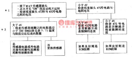
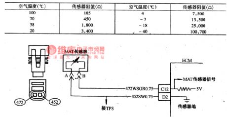
Fault code of 23 means the signal voltage of air temperature sensor is too high,(MAT) and the 25 means it is too low.Admission manifold air temperature sensor controls the signal voltage to ECM with a thermistor(see as Figure 18). ECM imposes a reference voltage(4~6V) on a sensor in No.427 circuit, when the air temperature is low, the resistance of the sensor (thermistor) is high, so ECM will get a high signal voltage. As the air gets warmer, the resistance of the sensor is getting lower, and the voltage is getting lower.
(View)
View full Circuit Diagram | Comments | Reading(1121)
| Pages:84/164 At 2081828384858687888990919293949596979899100Under 20 |
Circuit Categories
power supply circuit
Amplifier Circuit
Basic Circuit
LED and Light Circuit
Sensor Circuit
Signal Processing
Electrical Equipment Circuit
Control Circuit
Remote Control Circuit
A/D-D/A Converter Circuit
Audio Circuit
Measuring and Test Circuit
Communication Circuit
Computer-Related Circuit
555 Circuit
Automotive Circuit
Repairing Circuit