
Automotive Circuit
Index 82
The electric controlled oil injection system circuit of Tianjin Xiali TJ376Q-E
Published:2011/5/20 11:06:00 Author:Borg | Keyword: oil injection system, Tianjin Xiali

The TJ376Q-E electric controlled oil injection system belongs to a speed-density(D) oil multiple points injecting engine, whose main ingredients are as shown in Figure 5-1. Like other petrol injecting engine, it consists of admission system, oil supply system and electric control system.1.admission systemThe air comes through the filter(5) to remove the dust, and then goes past the throttle body(11) and the throttle and into the balance box(15) where it is re-distributed into each admission cylinder. When the admission valve is open, the air is inhaled into the cylinder with the petrol.
(View)
View full Circuit Diagram | Comments | Reading(959)
The circuit of Tianjin Xiali TJ710OE
Published:2011/5/20 3:41:00 Author:Borg | Keyword: circuit, Tianjin Xiali
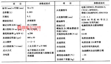
The new EFI of Tianjin Xiali started to be produced by DAZE Automobile Industry in 1997, it improved on 710OU. In TJ710OE, the engine is the TJ376Q-E e-control petrol injection engine,and the 710OU is fixed with the TJ376Q carburetor engine. After a lot of times of trials, we finally succeeded, and the car war launched to the market. The outline of the car has been improved, but the body and the chassis are almost the same with the former model. It it three-box, four-door and five-chairs, the maximum speed is more than 140km/h, the oil consumption at stable speed(60km/h) is less than 4.2L which is conforming to ECEl5-04. In a word, all the indexes are better than the former TJ710OU and TJ7100.
(View)
View full Circuit Diagram | Comments | Reading(497)
The air-conditioning control circuit of Xiali TJ7100.7100U
Published:2011/5/20 10:07:00 Author:Borg | Keyword: air-conditioning, control circuit, Xiali
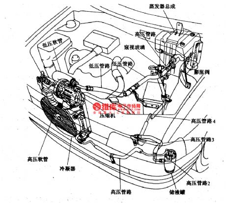
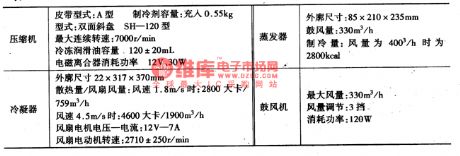
The cooling tube system of Xiali is seen in Figure 1, in the room, the cooling evaporator absorbs heat so that the refrigerant RI2 evaporates, the evaporant is in the condition of low-pressure(about 0.2 MPa) and low-temperature(about O℃) now. When RI2 converts from liquid in to gas, it has absorbed a lot of heat of vaporization, then the steamed RI2 flows into the cylinder, and it is turned into liquid again after pass the piston, but the temperature and pressure raises a lot(temperature is about 60-70℃ , pressure is between 1·0-1·5Mpa), and it is strained from the compressor to the condenser.
(View)
View full Circuit Diagram | Comments | Reading(513)
The steering and danger signal, lighting and headlight circuit of Tianjin Xiali TJ7100.7100U
Published:2011/5/20 20:40:00 Author:Borg | Keyword: steering, headlight, Tianjin Xiali
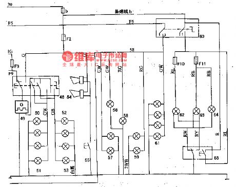
48-steering and danger warning switch; 49-steering flash; 50-left steering indicator; 51-left steering signal lamp(head, side,rear); 52-right steering indicator; 53-right steering signal lamp(head, side and rear); 54-loudspeaker; 55-loudspeaker key; 56-switch lamp; 57-head width lamp; 58-license lamp; 59-rear width lamp; 60-light switch; 61-instrument lighting lamp; 62-left head light; 63-right head light; 64-high beam indicator; 65-dimmer switch and overtaking signal switch (View)
View full Circuit Diagram | Comments | Reading(451)
The instrument, indicator and alarm lamp of Daewoo Racer
Published:2011/5/21 3:09:00 Author:Borg | Keyword: instrument, alarm lamp, Daewoo Racer
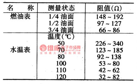
The H7 signal of engine rotating speed comes from the junior negative point of the igniting coil(connecting to igniting module); both the oil meter(H9) sensor and oil alarm switch are fixed in the oil tank, when the oil drops the minimum, the alarm lamp (E45) is on, but the car can run another 50KM. The water temperature meter(H8) and oil tank (H) share a stabilizer whose output voltage is 10V. The sensor parameters of these two meters are seen in Figure 6. One terminal of the electrooptical indicator(E36) connects to F13(No.15 wire), and the other connects with the juncture of the generator diode and the field coil.
(View)
View full Circuit Diagram | Comments | Reading(544)
the air-condtioning circuit of Daewoof Racer
Published:2011/5/21 3:25:00 Author:Borg | Keyword: air-condtioning, Daewoof Racer
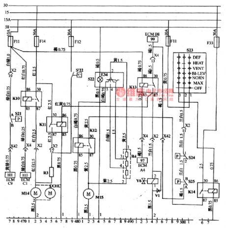
(11)the air-conditioning circuitAll the air-conditioning system is under the control of the switch S23. When it is at the OFF gear, the circuit is cut off, there is no heating or cooling. HEAT gear means the interior air is heated but not cooling. VENT gear means ventilation, there is no heating or cooling. DEF means defrost, the heater blows warm air to the windscreen, and the cooling system also can be turn on to dry the interior air(the temperature is auto controlled); BL-LEV gear means two levels of air is to be cooled or heated. NORN means normally cooling.
(View)
View full Circuit Diagram | Comments | Reading(606)
The oil injection control system and igniting system circuit of Daewoo-ESPERO
Published:2011/5/20 21:59:00 Author:Borg | Keyword: oil injection, control system, igniting system
See as Figure 3. the oil injection control system components of Daewoo-ESPERO
 (View)
View full Circuit Diagram | Comments | Reading(492)
The oil injection control system circuit of Daewoo-ESPERO
Published:2011/5/20 10:50:00 Author:Borg | Keyword: oil injection, control system, Daewoo-ESPERO
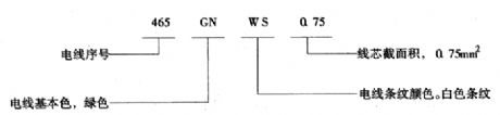

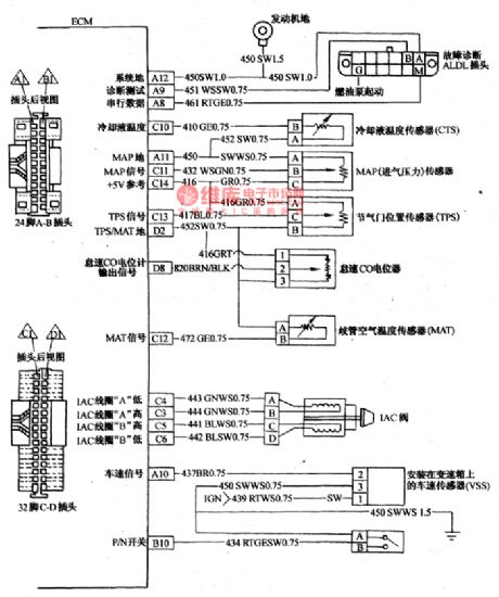
The connecting control relationship between oil pump relay, single point oil inject and the computer is shown in Figure 3. And the relationship between all the sensors, idling speed control valve(IAC) and ECU is shown in Figure 4.In figure 3, the ECM is the computer, the A1~A12、B1~B12、C1~C16 and D1~D16 on the border of ECM represent the plugs of a 24-lead A-B and a 32-lead C-D.The wire code consists of 4 parts, for example, between the pin ECMA1 and the pin 86 of oil pump relay, the No.465GNWSO.75 wire means the basic color of NO.465 wire is green, and it is with white strips, the cross-sectional area of wire core is 0.75m㎡.
(View)
View full Circuit Diagram | Comments | Reading(1660)
The control system sensor, fault diagnosis outlet and idling speed control circuit of ESPERO
Published:2011/5/20 21:53:00 Author:Borg | Keyword: control system, fault diagnosis outlet, idling speed control
The connection of the computer with igniting module, igniting coil, test coil(electricity signal generator) is seen in Figure 6.Notes: engine rotating speed is lower than 400rpm, EST connects with the earth, EST has no additional voltage; engine rotating speed is more than 400r/m, EST has additional reference voltage of 5V, EST has a control signal voltage delivered by ECM.Daewoo is fixed with computer controlled e-igniting system, the system has a electricity distributor but no touch spot. When the engine starts, the test coil got a crank position and engine rotating signal, and igniting module delivers the signal to ECM computer.
(View)
View full Circuit Diagram | Comments | Reading(720)
The single oil injection equipment (throttle body injection TBI) circuit of ESPERO
Published:2011/5/20 21:36:00 Author:Borg | Keyword: oil injection equipment, throttle body, ESPERO

1-air filter gasket; 5-oil inlet pipe nut of O shape; 6-oil outlet pipe nut of O shape; 10-flange gasket; 20-oil calculating components; 21-oil calculator fixing screw and gasket; 25-oil calculator to throttle gasket; 35-oil injector fixing screw; 36-spring seat; 66-pressure adjusting spring; 70-pressure adjustment valve component; 90-oil inlet nut; 91-oil pipe nut gasket; 96-oil outlet nut; 200-throttle body components. (View)
View full Circuit Diagram | Comments | Reading(2184)
The igniting system control circuit of Daewoo
Published:2011/5/20 9:40:00 Author:Borg | Keyword: igniting system, control circuit

See as figure 6. the igniting system control circuit of Daewoo (View)
View full Circuit Diagram | Comments | Reading(720)
The principle signal circuit of Daewoo Racer
Published:2011/5/21 21:47:00 Author:Borg | Keyword: signal circuit, Daewoo Racer

The backup lamp switch(S8) controls the lamp of E19 and E20, the turn lamp switch controls the left-hand signal lamps(E21 and E22) and left-hand turn indicator(E39), or right-hand signal lamps(E23 and E24) and right-hand indicator E40(see as instrument indicator). At the moment, the current of flash(K5) is provided by fuse F8 of No.15 circuit and controlled by the igniting switch. If the warning signal is delivered, the alarm lamp switch S9 is supposed to be press, and the current comes from No.30 circuit (positive pole of the battery) directly, so the left and right turn lamps flash at the same time, the flashing frequency is requested to be 85±10times/min.
(View)
View full Circuit Diagram | Comments | Reading(1196)
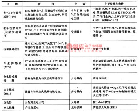
The principle parameter circuit of Daewoo sensor
Published:2011/5/20 22:19:00 Author:Borg | Keyword: principle parameter, Daewoo
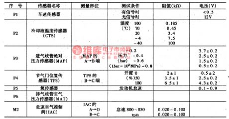
The principle parameter circuit of Daewoo sensor
(View)
View full Circuit Diagram | Comments | Reading(505)
The oil injection and air-conditioner control circuit of Daewoo-ESPERO
Published:2011/5/20 21:22:00 Author:Borg | Keyword: oil injection, air-conditioner, Daewoo-ESPERO

The connection of ECM with magnetic clutch, air-conditioner cooling fan and high-low voltage switch is as shown in Figure 7.
The voltage values of computer connectors are listed in Table 13-4, and the test position of the pins are shown in Figure 8. Notice the positions of A1~A12,B1~B12,C1~C16 and D1~D16.In the upper of the figure shows the pin sequence code, wire colors and voltage of plugs A-B, the left upper is pins of A1~A12, right upper is pins of B1~B12; in the lower part of the figure shows the pin sequence code and wire colors of C-D, and the left lower is pins of c1~D16. (View)
View full Circuit Diagram | Comments | Reading(1491)
The oil pump and fault test lamp circuit of Daewoo Racer
Published:2011/5/21 22:39:00 Author:Borg | Keyword: oil pump, fault test lamp, Daewoo Racer

E1-the test lamp of fast repairing engine; K1-the e-controller of the generator; K2-oil pump relay; M3- oil pump electromotion; S2-A/T switch; S3-brake switch; S26-engine oil pressure alarm switch; Y4-torque transmission and clutch magnetic valve(auto charger); X-fault diagnosis outlet (View)
View full Circuit Diagram | Comments | Reading(1841)
The e-control injection system circuit of Daewoo Racer
Published:2011/5/21 23:58:00 Author:Borg | Keyword: oil injection system, Daewoo


The emission of Racer engine is 1.5L, single top cam shaft of 4 in-line cylinders, the oil supply system is fixed with a TBI throttle body--the central oil injection (single point) system. And on the higher part of the throttle center, there is a multiple jet fulfilling oil injection, and there is a pressure adjuster, idling speed control stepper motor, throttle position sensor, air filter control, oil channel interface, etc. And its size is the same as carburettor.1.oil system consists of oil box, oil pump M3, oil pipe channel, etc.
(View)
View full Circuit Diagram | Comments | Reading(2355)
The power supply,stating, igniting, instrument and indicator circuit of Tianjin Xiali TJ7100 and 7100U
Published:2011/5/20 21:09:00 Author:Borg | Keyword: power supply, indicator, instrument
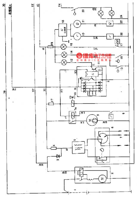
A,b,.c-fusible links; Fl-FI4-fuse; 1-battery; 2-starter; 3-separated diode; 4-additional resistance; 5-igniting coil(close flux); 6-electricity distributor; 7-spark piston; 7a-fan motor relay; 8-radiator fan motor; 9-temperature control switch; 10-oil cutting magnetic valve; 11-integral AC electricity generator; 12-charging indicator; 13-hand brake switch; 14-brake fluid level alarm indicator; 15-brake fluid switch; 16-oil pressure alarm lamp; 17-oil alarm switch; 18-pressure stabilizer (View)
View full Circuit Diagram | Comments | Reading(456)
The room lamp, wiper/washer,air-conditioning and radio circuit of Tianjin Xiali 7100 and 7100U
Published:2011/5/20 20:53:00 Author:Borg | Keyword: room lamp, wiper/washer, air-conditioning
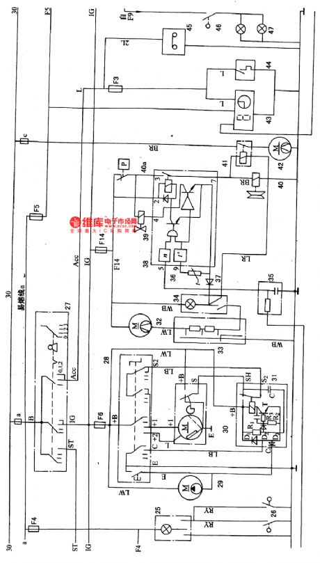
25-room lamp; 26-door control switch; 27-igniting switch; 28-wiper/washer switch(inside the combination switch); 29-washing motor; 30-wiper motor; 31-interval relay; 39-air-conditioning blow motor; 33-air blow transmission slipping switch; 34-air-conditioning switch; 35-engine steering signal filter; 36-thermistor; 37-diode; 38-air-conditioning control amplifier; 39-idling speed raising magnetic valve; 40-the magnetic clutch of air-conditioning compressor; 41a-pressure switch; 41-condenser fan motor relay; 42-condenser fan motor; 43-digital clock (View)
View full Circuit Diagram | Comments | Reading(893)
The engine fault codes of Daewoo Racer
Published:2011/5/21 22:23:00 Author:Borg | Keyword: fault codes, Daewoo Racer
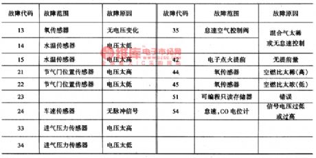
When the igniting switch is ON , short-connect the terminals, A and B, of the general detection outlet X1, so the fault code can be got if the fast repairing motor indicator flashes, then check the following table and find out the meaning and the cause of the code; if we want to remove the code, just cut off the igniting switch after dealing with the fault, and take down the fuse FI and install back in 10 seconds. The fault codes of Daewoo-Racer are seen in Table 5. The engine fault codes of Daewoo-Race
(View)
View full Circuit Diagram | Comments | Reading(1208)
The cigarette lighter and room lamp circuit of Daewoo Racer
Published:2011/5/21 21:30:00 Author:Borg | Keyword: cigarette lighter, room lamp, Daewoo Racer

(6)cigarette lighter, clock, room lamp and seat belt(see as Figure 8)Under the fuse F13(20a), there are glove box lamp(E26), cigarette lighter(R1) and clock(H1), cigarette lighter lamp(E27) and ashtray light(E28). The engine chamber lamp(E29) still connects with the No.58 circuit and it is under the control of the light switch(S4).The room lamp(E30) and trunk lamp(E31) connect with the fuse of F15(20A)(see as Figure 9), and they are under the control of their own switch(hand or mechanic control, such as the door control switchs of S13 and S14). We can see in Figure 8 that when the igniting switch is on, and the seatbelt is not fixed, the switch of S1 will be on.
(View)
View full Circuit Diagram | Comments | Reading(1008)
| Pages:82/164 At 2081828384858687888990919293949596979899100Under 20 |
Circuit Categories
power supply circuit
Amplifier Circuit
Basic Circuit
LED and Light Circuit
Sensor Circuit
Signal Processing
Electrical Equipment Circuit
Control Circuit
Remote Control Circuit
A/D-D/A Converter Circuit
Audio Circuit
Measuring and Test Circuit
Communication Circuit
Computer-Related Circuit
555 Circuit
Automotive Circuit
Repairing Circuit