Automotive Circuit
Electronic Bird Repeller (2)
Published:2011/5/20 5:13:00 Author:Sue | Keyword: Electronic, Bird, Repeller | From:SeekIC

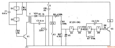
When S is on, multivibrator generates signals. T generates 300V voltage and charges C2. When D3's voltage reaches 4.5V, D4's output has high level, making VD2 disconnected. Low frequency oscillator stops working. V2 is connected and YV is connected. The gong is knocked to make a sound.
When YV works, C2's voltage is used and C3's voltage is higher than 4.5V. D4's output has low level and VD2 is connected. V2 is disconnected, K and YV are released and C2 begins to charge. There will be anautomatic knock at the gang.
Reprinted Url Of This Article:
http://www.seekic.com/circuit_diagram/Automotive_Circuit/Electronic_Bird_Repeller_2.html
Print this Page | Comments | Reading(3)

Article Categories
power supply circuit
Amplifier Circuit
Basic Circuit
LED and Light Circuit
Sensor Circuit
Signal Processing
Electrical Equipment Circuit
Control Circuit
Remote Control Circuit
A/D-D/A Converter Circuit
Audio Circuit
Measuring and Test Circuit
Communication Circuit
Computer-Related Circuit
555 Circuit
Automotive Circuit
Repairing Circuit
Code: