Automotive Circuit
Electronic Bird Repeller (1)
Published:2011/5/20 5:06:00 Author:Sue | Keyword: Electronic, Bird, Repeller | From:SeekIC

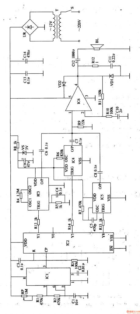
When S is on, 220V voltage will provide IC1,IC2,IC6,IC3,IC5 with working voltage.After the clockpulse generator begins to oscillate, IC2 will count the input pulse.
When the first pulse comes, Y1 outputs high level, and IC3 begins to work. O/P will output firecracker sound signals. BL will make a sound of firecracker.
When the 5th pulse comes, Y5 outputs high level, and IC4 begins towork. O/P will output sound signals and BL will make a sound of Di di, be careful .
When the 8th pulse comes, Y8 outputs high level, and IC5 begins to work. O/P will output bark signals and BL will make a barking sound.
When the 11th pulse comes, Y1 outputs high level again, BL makes a sound of firecracker. The circuit works in this order to drive birds away.
Reprinted Url Of This Article:
http://www.seekic.com/circuit_diagram/Automotive_Circuit/Electronic_Bird_Repeller_1.html
Print this Page | Comments | Reading(3)

Article Categories
power supply circuit
Amplifier Circuit
Basic Circuit
LED and Light Circuit
Sensor Circuit
Signal Processing
Electrical Equipment Circuit
Control Circuit
Remote Control Circuit
A/D-D/A Converter Circuit
Audio Circuit
Measuring and Test Circuit
Communication Circuit
Computer-Related Circuit
555 Circuit
Automotive Circuit
Repairing Circuit
Code: