
Amplifier Circuit
Index 154
RGB_VIDEO_AMPLIFIER
Published:2009/6/24 21:41:00 Author:May
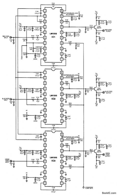
This circuit is a three-channeL RGB video amplifer with individual brightness,black level and drive controls. (View)
View full Circuit Diagram | Comments | Reading(798)
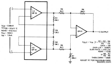
DIFFERENTIAL_INPUT_INSTRUMENTATION_AMPLIFIER_WITH_HIGH_COMMON_MODE_REJECTION
Published:2009/6/24 21:45:00 Author:Jessie
View full Circuit Diagram | Comments | Reading(677)
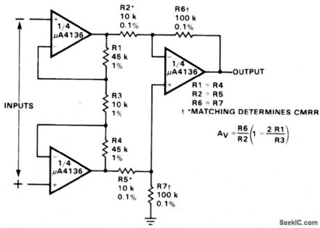
TRIPLE_OP_AMP_INSTRUMENTATION_AMPLIFIER
Published:2009/6/24 21:43:00 Author:Jessie
View full Circuit Diagram | Comments | Reading(619)
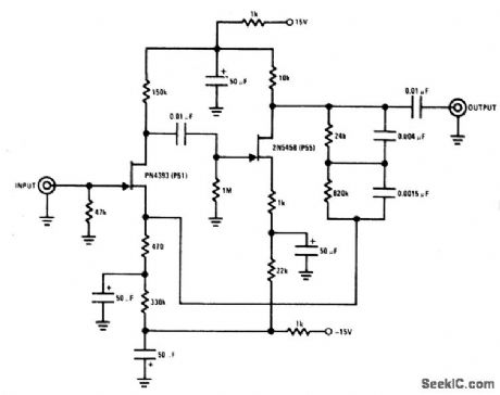
INSTRUMENTATION_AMPLIFIER
Published:2009/6/24 21:42:00 Author:Jessie

Instrumentation amplifiers (differential amplifiers) are specifically designed to extract and amplify small differential signals from much larger common mode voltages. To serve as building blocks in instrumentation amplifiers, op amps must have very low offset voltage drift, high gain and wide bandwidth.The HA-4620/5604 is suited for this application. The optional circuitry makes use of the fourth amplifier section as a shield driver which enhances the ac common mode rejection by nullifying the effects of capac itance -to-ground mismatch between input conductors. (View)
View full Circuit Diagram | Comments | Reading(1197)
THERMOCOUPLE_AMPLIFIER_WITH_COLD_JUNCTION_COMPENSATION
Published:2009/6/24 4:22:00 Author:May
View full Circuit Diagram | Comments | Reading(1275)
SIMPLE_AMPLIFIER_FOR_PHOTOTRANSISTORS
Published:2009/6/24 3:56:00 Author:May

This simple amplifier will work well with just about any phototransistor. The 741, although designed to operate with a split supply, will work with a single-sided supply as well. (View)
View full Circuit Diagram | Comments | Reading(845)
CRYSTAL_CHECKER
Published:2009/6/24 20:59:00 Author:Jessie

Use this circuit for checking fundamental HF crystals on a 'Go-No-Go' basis. An untuned Colpitts oscillator drives a voltage multiplier rectifier and a current amplifier. If the crystal oscillates, Q2 conducts and the LED lights. A3 or 6V, 40mA bulb could be substituted for the LED. (View)
View full Circuit Diagram | Comments | Reading(4)
RECEIVER_PREAMP
Published:2009/6/24 4:37:00 Author:May
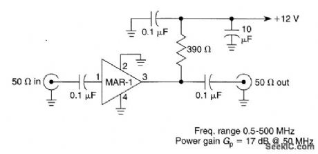
Suitable for HF and VHF receivers, this preamplifier can be mounted on the back of the receiver for a boost in gain. Useful gain is about 17 dB at 50 MHz (View)
View full Circuit Diagram | Comments | Reading(2786)
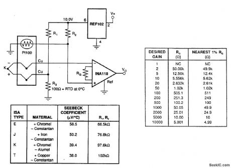
PRECISION_RTD_AMPLIFIER_CIRCUIT_FOR+5_V
Published:2009/6/24 4:23:00 Author:May
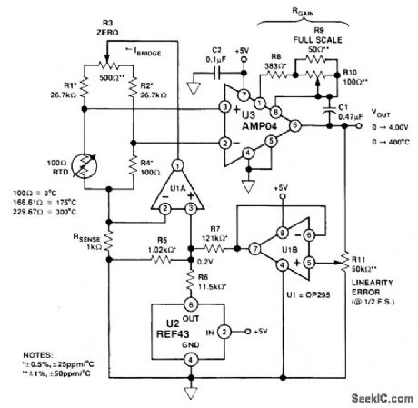
This circuit uses a platinum resistance temperature device to sense temperature. It has a range of 0 to 300℃. The RTD bridge is driven with a regulated 200-μA current to minimize self heating of the RTD. A 5-V supply is used. (View)
View full Circuit Diagram | Comments | Reading(913)
TAPE_PLAUBACK_AMPLIFIER
Published:2009/6/24 3:57:00 Author:May
View full Circuit Diagram | Comments | Reading(575)
MAGNETIC_PHONO_PREAMPLIFIER
Published:2009/6/24 3:51:00 Author:May

View full Circuit Diagram | Comments | Reading(766)
TAPE_RECORDING_AMPLIFIER
Published:2009/6/24 3:49:00 Author:May

View full Circuit Diagram | Comments | Reading(609)
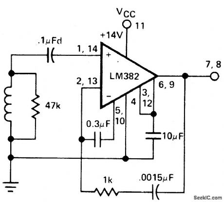
TAPE_PREAMPLIFIER_NAB_EQUALIZATION
Published:2009/6/24 3:49:00 Author:May
View full Circuit Diagram | Comments | Reading(507)
FLAT_RESONSE_AMPLIFIER_FIXED_GAIN_CONFIGURATION
Published:2009/6/24 3:55:00 Author:Jessie
View full Circuit Diagram | Comments | Reading(476)
PREAMPLIFIER_WITH_RIAA_NAB_COMPENSATION
Published:2009/6/24 3:54:00 Author:Jessie
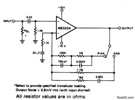
View full Circuit Diagram | Comments | Reading(1118)
HIGH_GAIN_INVERTING_AC_AMPLIFIER
Published:2009/6/24 3:53:00 Author:Jessie
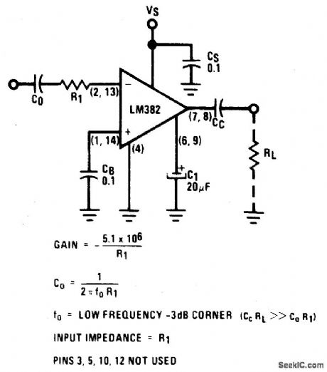
View full Circuit Diagram | Comments | Reading(516)
ADJUSTABLE_GAIN_NONINVERTING_AMPLIFIER
Published:2009/6/24 3:53:00 Author:Jessie
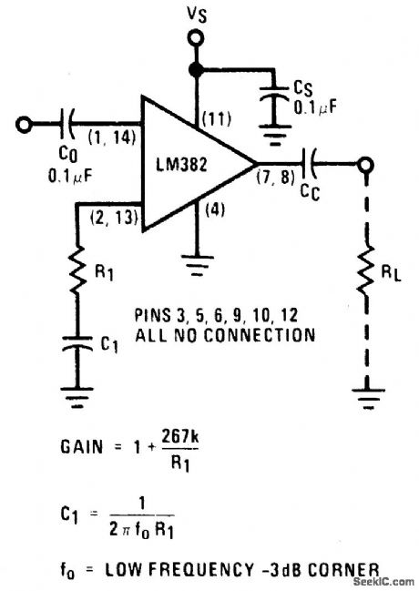
View full Circuit Diagram | Comments | Reading(569)
MAGNETIC_PICKUP_PHON0_PREAMPLIFIER
Published:2009/6/24 3:44:00 Author:May
This preamplifier provides proper loading to a reluctance phono cartridge. It provides approximately 35 dB of galn at 1 kHz (2.2 mV input for 100 mV output).It features (S+N)/N ratio of better than -70 dB (referenced to 10 mV input at 1 kHz) and has a dynamic range of 84 dB (referenced to 1 kHz). The feedback provides for RIAA equalization. (View)
View full Circuit Diagram | Comments | Reading(810)
PHONO_[REAM_RIAA_EQUALIZATION
Published:2009/6/24 3:52:00 Author:Jessie
View full Circuit Diagram | Comments | Reading(745)
TELEPHONE_BELL_AMPLIFIER
Published:2009/6/24 3:43:00 Author:May
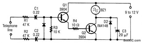
Telephone bell amplifier circuit will let you hear (or see) an enhanced alarm if you are away from your telephone. (View)
View full Circuit Diagram | Comments | Reading(677)
| Pages:154/250 At 20141142143144145146147148149150151152153154155156157158159160Under 20 |
Circuit Categories
power supply circuit
Amplifier Circuit
Basic Circuit
LED and Light Circuit
Sensor Circuit
Signal Processing
Electrical Equipment Circuit
Control Circuit
Remote Control Circuit
A/D-D/A Converter Circuit
Audio Circuit
Measuring and Test Circuit
Communication Circuit
Computer-Related Circuit
555 Circuit
Automotive Circuit
Repairing Circuit