
Amplifier Circuit
Index 152
HIGH_SPEED_6_BIT_A_D_BUFFER
Published:2009/6/24 22:47:00 Author:May

View full Circuit Diagram | Comments | Reading(458)
HIGH_IMPEDANCE_LOW_CAPACITANCE_WIDEBAND_BUFFER
Published:2009/6/24 22:46:00 Author:May
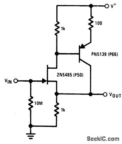
The 2N5485 has low input capacitance which makes this compound series-feedback buffer a wide-band unity gain amplifier. (View)
View full Circuit Diagram | Comments | Reading(804)
SINGLE_SUPPLY_AC_BUFFER_AMPLIFIER
Published:2009/6/24 22:43:00 Author:May
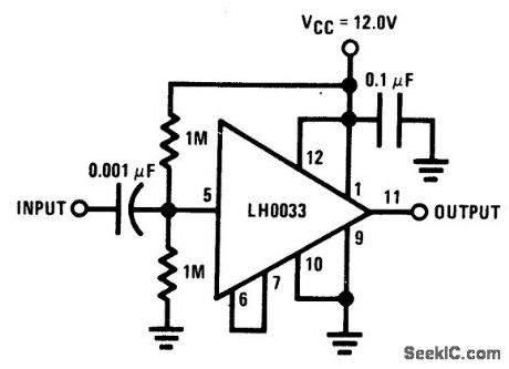
The input is dc biased to mid-operating point and is ac coupled. Its input impedance is approximately 500K at low frequencies. For dc loads referenced to ground, the quiescent cur-rent is increased by the load current set at the input dc bias voltage. (View)
View full Circuit Diagram | Comments | Reading(0)
SINE_WAVE_OUTPUT_BUFFER_AMPLIFIER
Published:2009/6/24 22:42:00 Author:May
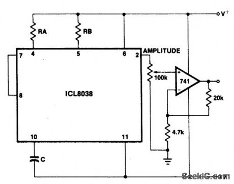
The sine wave output has a relatively high output impedance (1K typ). The circuit provides buffering, gain, and amplitude adjust ment. A simple op amp follower could also be used. (View)
View full Circuit Diagram | Comments | Reading(583)
PHOTODIODE_AMPLIFIER
Published:2009/6/24 22:42:00 Author:May
View full Circuit Diagram | Comments | Reading(2162)
FOUR_QUADRANT_PHOTO_CONDUCTIVE_DETECTOR_AMPLIFIER
Published:2009/6/24 22:30:00 Author:May
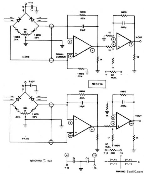
Use this circuit to sense four quadrant motion of a light source. By proper summing of the signals from the X and Y axes, four quadrant output may be fed to an X-Y plotter, oscilloscope, or computer for simulation. IC = NE/SE5514 (View)
View full Circuit Diagram | Comments | Reading(1375)
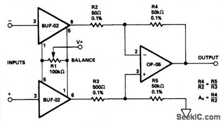
HIGH_IMPEDANCE_LOW_DRIFT_INSTRUMENTATION_AMPLIFIER
Published:2009/6/24 22:24:00 Author:May
View full Circuit Diagram | Comments | Reading(475)
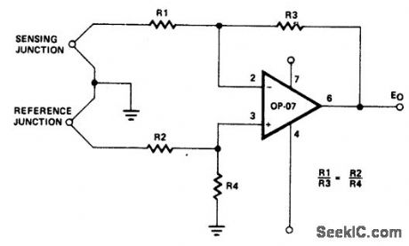
1HIGH_STABILITY_THERMOCOUPLE_AMPLIFIER
Published:2009/6/24 22:23:00 Author:May
View full Circuit Diagram | Comments | Reading(606)
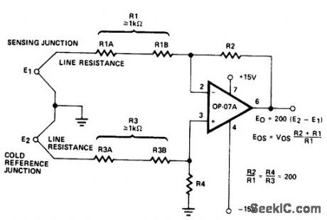
HIGH_STABILITY_THERMOCOUPLE_AMPLIFIER
Published:2009/6/24 22:22:00 Author:May
View full Circuit Diagram | Comments | Reading(1832)
PRECISION_FET_INPUT_INSTRUMENTATION_AMPLIFIER
Published:2009/6/24 22:21:00 Author:May

View full Circuit Diagram | Comments | Reading(508)
VARIABLE_GAIN_AMPLIFIER
Published:2009/6/24 22:18:00 Author:May
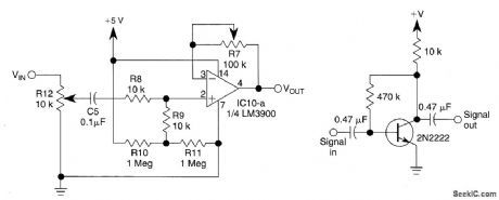
This circuit uses 1/4 of an LM3900 to build a simple variable-gain front end for an oscilloscope. R7 is the gain control. Also shown is a simple preamp if you need more than 10X of gain. (View)
View full Circuit Diagram | Comments | Reading(2028)
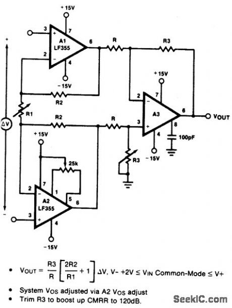
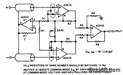
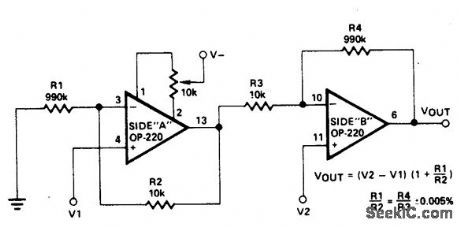
VERY_HIGH_IMPEDANCE_INSTRUMENTATION_AMPLIFIER__
Published:2009/6/24 22:17:00 Author:May
View full Circuit Diagram | Comments | Reading(512)
HIGH_SPEED_INSTRUMENTATION_AMPLIFIER_
Published:2009/6/24 22:16:00 Author:May
View full Circuit Diagram | Comments | Reading(465)
HIGH_IMPEDANCE_DIFFERENTIAL_AMPLIFIER
Published:2009/6/24 22:16:00 Author:May
View full Circuit Diagram | Comments | Reading(0)
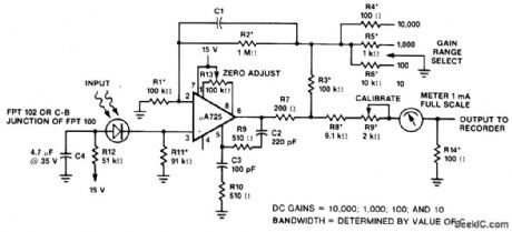
LOW_DRAIN_METER_AMPLIFIER
Published:2009/6/24 22:16:00 Author:May
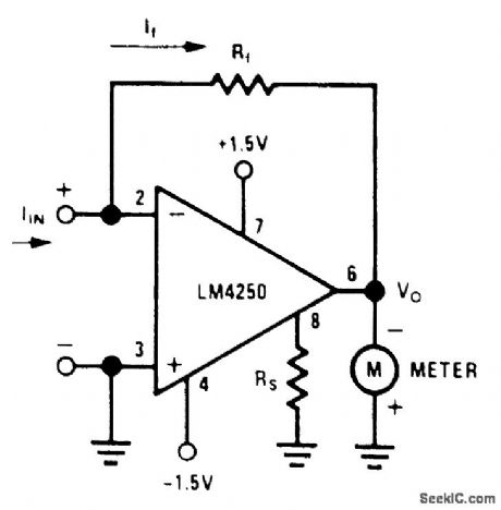
Meter amplifiers normally require one or two 9-V transistor batteries. Because of the heavy cur-rent drain on these supplies, the meters must be switched to the OFF position when not in use. The meter circuit described here operates on two 1.5-V flashlight batteries and has a quiescent power drain so low that no on/off switch is needed. A pair of Eveready No. 950 D cells will serve for a min-irnum of one year without replacement. As a dc ammeter, the circuit will provide current ranges as low as 100 nA full-scale.
The basic meter amplifier circuit shown is a current-to-voltage converter. Negative feedback around the amplifier ensures that currents IIN and If are always equal, and the high gain of the op amp ensures that the input voltage between pins 2 and 3 is in the microvolt region. Output voltageVO is therefore equal to -IfRf. Considering the ±1.5-V sources (±1.2 V end of life) a practical value ofVO for full-scale meter deflection is 300 mV. With the master bias-current setting resistor (RS) set at 10 MΩ, the total quiescent current drain of the circuit is 0.6μA for a total power supply drain of 1.8 pW. The irtput bias current, required by the amplifier at this low level of quiescent current, is in the range of 600μA. (View)
View full Circuit Diagram | Comments | Reading(681)
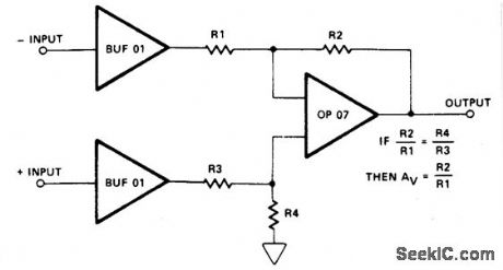
DIFFERENTIAL_INPUT_INSTRUMENTATION_AMPLIFIER_
Published:2009/6/24 22:15:00 Author:May

View full Circuit Diagram | Comments | Reading(599)
3INSTRUMENTATION_AMPLIFIER
Published:2009/6/24 22:13:00 Author:May
View full Circuit Diagram | Comments | Reading(691)
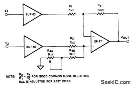
INSTRUMENTATION_AMPLIFIER(TWO_OP_AMP_DESIGN)
Published:2009/6/24 22:12:00 Author:May
View full Circuit Diagram | Comments | Reading(571)
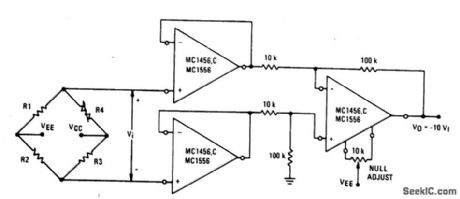
HIGH_IMPEDANCE_BRIDGE_AMPLIFIER
Published:2009/6/24 22:08:00 Author:May
View full Circuit Diagram | Comments | Reading(588)
HIGH_GAIN_DIFFERENTIAL_INSTRUMENTATION_AMPLIFIER
Published:2009/6/24 22:07:00 Author:May
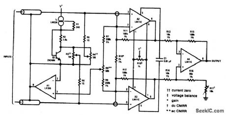
This circuit includes input guarding, cable bootstrapping, and bias current compensation. Differential bandwidth is reduced by C1 which also makes common-mode rejection less dependent on matching of input amplifiers. (View)
View full Circuit Diagram | Comments | Reading(575)
| Pages:152/250 At 20141142143144145146147148149150151152153154155156157158159160Under 20 |
Circuit Categories
power supply circuit
Amplifier Circuit
Basic Circuit
LED and Light Circuit
Sensor Circuit
Signal Processing
Electrical Equipment Circuit
Control Circuit
Remote Control Circuit
A/D-D/A Converter Circuit
Audio Circuit
Measuring and Test Circuit
Communication Circuit
Computer-Related Circuit
555 Circuit
Automotive Circuit
Repairing Circuit