
Amplifier Circuit
Index 150
PRECISION_PHOTODIODE_COMPARATOR
Published:2009/6/25 2:28:00 Author:May

View full Circuit Diagram | Comments | Reading(1089)
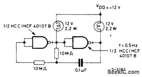
22_WATT_INCANDESCENT_LAMP_DRIVER
Published:2009/6/25 2:18:00 Author:May
View full Circuit Diagram | Comments | Reading(540)
BUTLER_EMITTER_FOLLOWER_OSCILLATOR(100_MHz)
Published:2009/6/25 2:13:00 Author:May

Circuit NotesThis circuit has good performance without any parasitics because emitter follower amplifier has a gain of only one with built-in negative feedback to stabilize its gain. (View)
View full Circuit Diagram | Comments | Reading(1139)
NEON_LAMP_DRIVER
Published:2009/6/25 2:09:00 Author:May

View full Circuit Diagram | Comments | Reading(524)
LIMIT_COMPARATOR_1
Published:2009/6/25 1:51:00 Author:May

View full Circuit Diagram | Comments | Reading(833)
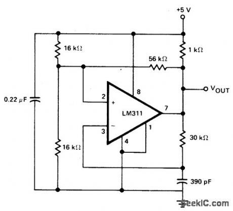
COMPARATOR_CLOCK_CIRCUIT
Published:2009/6/25 1:50:00 Author:May
View full Circuit Diagram | Comments | Reading(516)
DOUBLE_ENDED_LIMIT_COMPARATOR
Published:2009/6/25 1:49:00 Author:May
View full Circuit Diagram | Comments | Reading(626)
LIMIT_COMPARATOR
Published:2009/6/25 1:49:00 Author:May

View full Circuit Diagram | Comments | Reading(579)
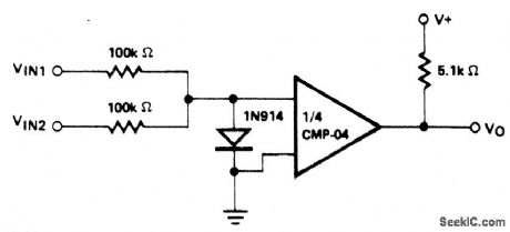
OPPOSITE_POLARITY_INPUT_VOLTAGE_COMPARATOR
Published:2009/6/25 1:48:00 Author:May
View full Circuit Diagram | Comments | Reading(502)
WINDOW_COMPARATOR_1
Published:2009/6/25 1:44:00 Author:May
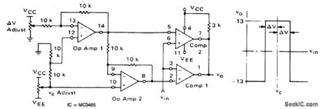
View full Circuit Diagram | Comments | Reading(693)
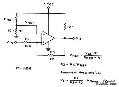
INVERTING_COMPARATOR_WITH_HYSTERESIS
Published:2009/6/25 1:43:00 Author:May
View full Circuit Diagram | Comments | Reading(1329)
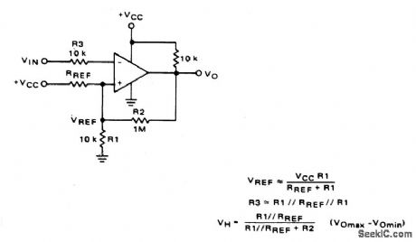
NONINVERTING_COMPARATOR_WITH_HYSTERESIS
Published:2009/6/25 1:42:00 Author:May
View full Circuit Diagram | Comments | Reading(2683)
COMPARATOR_WITH_TIME_OUT
Published:2009/6/25 1:42:00 Author:May
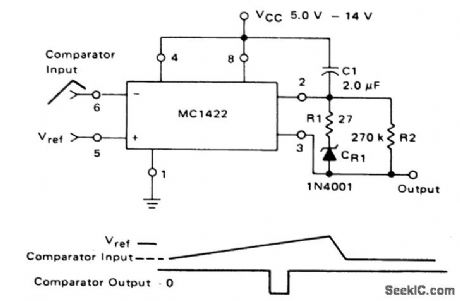
The MC1422 is used as a comparator with the capability of a timing output pulse when the inverting input (Pin 6) is ≥the noninverting input (Pin 5). The frequency of the pulses for the values of R2 and C1 as shown is approxi-mately 2.0 Hz, and the pulse width 0.3 ms. (View)
View full Circuit Diagram | Comments | Reading(541)
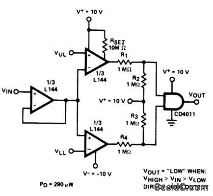
WINDOW_COMPARATOR_DRIVING_HIGH_LOW_LAMPS
Published:2009/6/25 1:40:00 Author:May

View full Circuit Diagram | Comments | Reading(836)
WINDOW_COMPARATOR
Published:2009/6/25 1:39:00 Author:May

This circuit gives an output (which in this case is 0V) when an input voltage lies in be-tween two specified voltages. When it is out-side this window, the output is positive. The two op amps are used as voltage comparators. When Vin is more positive than Vref (upper) the output of IC1 is positive and Dl is forward biased. Otherwise the output is negative, D1 reverse biased and hence Vout is 0V. Similarly, when Vin is more negative than Vref (lower), the output of IC2 is positive; D2 is forward biased and this Vout is positive. Otherwise Vout is 0V. When Vin lies within the window set by the reference voltages, Vout is 0V. (View)
View full Circuit Diagram | Comments | Reading(1371)
DUAL_LIMIT_COMPARATOR
Published:2009/6/25 1:37:00 Author:May

This circuit gives a positive output when the input voltage exceeds 8.5 volts. Between these limits the output is negative. The posi-tive limit point is determined by the ratio of R1, R2, and the negative point by R1, R3. The forward voltage drop across the diodes must be allowed for. The output may be inverted by reversing the inputs to the op amp. The 709 is used without frequency compensation. (View)
View full Circuit Diagram | Comments | Reading(992)
DIODE_FEEDBACK_COMPARATOR
Published:2009/6/25 1:34:00 Author:May

This circuit can drive an LED display with constant current independently of wide power supply voltage changes. It can operate with a power supply range of at least 4V to 30V. With 10M resistances for R2 and R3 and the inverting input of the comparator grounded, the cir-cuit becomes an LED driver with very high input impedance. The circuit can also be used in many other applications where a controllable constant current source is needed. (View)
View full Circuit Diagram | Comments | Reading(1143)
COMPARATOR_WITH_VARIABLE_HYSTERESIS_WITHOUT_SHIFTING_INITIAL_TRIP_POINT
Published:2009/6/25 1:34:00 Author:May

An operational amplifier can be used as a convenient device for analog comparator appli-cations that require two different trip points. The addition of a positive-feedback network introduces a precise variable hysteresis into the usual comparator switching action. Such feedback develops two comparator trip points centered about the initial trip point or refer-ence point. The voltage difference, AY, be-tween the trip points can be adjusted by varying resistor R2. When the output voltage is taken from the zener diode, as shown, it switches between zero and Vz, the zener voltage. (View)
View full Circuit Diagram | Comments | Reading(1446)
PIEZO_MICROPOSITIONER_DRIVER
Published:2009/6/24 23:43:00 Author:May
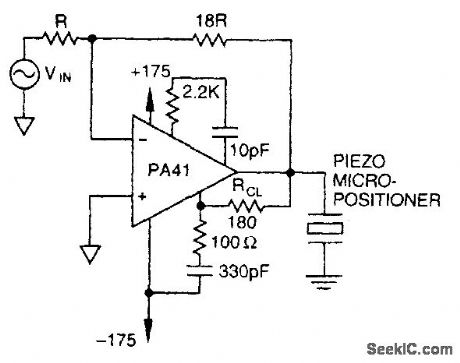
The PA41 from Apex Microtechnology is used here to drive a piezoelectric micropositioner. The drive voltage is less than 20 V p-p at input. (View)
View full Circuit Diagram | Comments | Reading(614)
PIEZO_DRIVER
Published:2009/6/24 23:42:00 Author:May

Using a PA41 from Apex Microtechnology, this monolithic amplifier is capable of 350-V operation and delivers 660 V p-p in a bridge circuit. (View)
View full Circuit Diagram | Comments | Reading(1358)
| Pages:150/250 At 20141142143144145146147148149150151152153154155156157158159160Under 20 |
Circuit Categories
power supply circuit
Amplifier Circuit
Basic Circuit
LED and Light Circuit
Sensor Circuit
Signal Processing
Electrical Equipment Circuit
Control Circuit
Remote Control Circuit
A/D-D/A Converter Circuit
Audio Circuit
Measuring and Test Circuit
Communication Circuit
Computer-Related Circuit
555 Circuit
Automotive Circuit
Repairing Circuit