
Circuit Diagram
Index 462
1.5v LCD circuit diagram
Published:2011/9/15 1:51:00 Author:Rebekka | Keyword: 1.5v LCD

Motorola's MC1440 CMOS integrated circuit has the functions of completion time, display calendar. 32.768KHZ NT cut-type quartz crystal and fine-tuning capacitor can generate time-base signal. The monitor circuit only uses 1.5V AAA battery, and the watch circuit can work more than one year, and accuracy is less than the ± 1min. The voltage tripler composed of MBD101 Schottky diode can switch the 1.5V battery output voltage into 4V for the LCD monitor. (View)
View full Circuit Diagram | Comments | Reading(1880)
MC3359 radiofrequency receiver circuit diagram
Published:2011/9/15 1:44:00 Author:Rebekka | Keyword: radiofrequency receiver

Here is the schematic diagram of the MC3359 radiofrequency receiver circuit diagram:
MC3359 is the RF receiver circuit, and it can receive 315MHZ, 434MHZ bandwidth, and the IF bandwidth is 500KHZ. (View)
View full Circuit Diagram | Comments | Reading(3678)
JFET gate grounding preamplifier circuit diagram
Published:2011/9/15 1:38:00 Author:Rebekka | Keyword: JFET gate grounding preamplifier


Figure 1-1 is the example of joint types FET 2SK125(SONY) grounded gate amplifier. So when you use the gate grounding circuit, you could separate the input and output by using the grounding gate electrode on printing copper foil. The power gain of the circuit is about 10~12dB, NF is about 2dB. The LC value in the circuit change with frequency. You should choose table 1-1, and L1, L2 are at toroidal core amine line of poly resin. The diameter is about 0.3mm. It should insert in the substrate directly to avoid producing stray capacitance. You could Adding a source of resistor where you want to adjust and keep the drain current being about 10mA. In addition, adjusting trimmer condenser can get the highest sensitivity. (View)
View full Circuit Diagram | Comments | Reading(3096)
1M ~ 50MHZ 1W broadband power amplifier circuit diagram
Published:2011/9/15 1:35:00 Author:Rebekka | Keyword: broadband power amplifier

The picture shows the 1W wide-broadband power amplifier with frequency in 1 ~ 50MHz and using 2SC1970; Input and output coils use broadband transformer composed of toroidal winding for impedance conversion. 2SC1970 is the 170MHz power transistor, so it can be used for the VHF band broadband amplifier. In the circuit , the coupling capacitor (CoupIingCapacitor) and Bypass Capacitor are connected with 2 to 3 0.01μF ceramic capacitor in parallel, the most important thingis to reduce the impedance (Impedance), at the same time, the current flows the channel is also wider. (View)
View full Circuit Diagram | Comments | Reading(2718)
Light pen connector circuit diagram
Published:2011/9/15 1:27:00 Author:Rebekka | Keyword: light pen connector
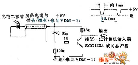
If you put any high-quality photodiodes in a waste barrel and take it to fluorescence-screen display, you can pick up optical signals. If the diode is put into plastic lens, you need to sand Lens side by emery cloth to make the light angle. The set is desgned for matching VDM-1 display terminal. When you move the light pen by the face of the screen, the cathode ray oscilloscope can be used for monitoring the outcoming signal of the circuit. In the dark space of the face of the screen, it produces 5V DC level; in the bright region, the level will fall down. (View)
View full Circuit Diagram | Comments | Reading(1078)
Three-phase three-wire system open phase protection circuit diagram
Published:2011/9/15 1:26:00 Author:Rebekka | Keyword: Three-phase three-wire system , open phase protection
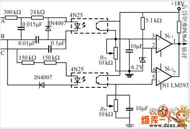
This is an openphase protection circuit for three-phase three-wire power supply. A, B, C are lack of any one phase, the optocoupler output level is lower than the inverting input of the comparator reference voltage. The comparator outputs low blockade PWM to drive signal, turn off the power.As well as the polarity of the comparator input changes, PWM signals can be blocked with a high level.
(View)
View full Circuit Diagram | Comments | Reading(2098)
10M-1200MHZ and μPC1651G broadband amplifier circuit diagram
Published:2011/9/14 21:41:00 Author:Rebekka | Keyword: broadband amplifier circuit

μPC1651G(Japanese electrical apparatus) series use high-frequency broadband amplifier. Micro-disc shape(Micro Disk Type). Frequency coverage is 10M~1200MHz(@-3dB), and the gain is 19dB(@f=500MHz). NF is about 5dB, so it's not good to use receiver preamplifier. But there is not much effect on using receiver preamplifier and IF amplifying circuit. Figure 1 is broadband preamplifier composed of μPC1651G. Although it has a simple structure, you should pay attention to the effect of lead inductance when youwant to get1200MHz, so it is better to use short wiring. The circuit cases use broadband amplifier composed of glass epoxy double-sided substrate. The bypass capasitor of power terminal should be connected between IC power supply and ground. It should be near to IC.
(View)
View full Circuit Diagram | Comments | Reading(1498)
12V simple regulator circuit diagram 3
Published:2011/9/26 21:17:00 Author:Rebekka | Keyword: simple regulator

View full Circuit Diagram | Comments | Reading(1270)
Operational amplifier general zero setting method circuit diagram
Published:2011/9/26 21:21:00 Author:Rebekka | Keyword: Operational amplifier , zero setting method

The figure shows a simple common zero seting circuit. Its integrated chip can be used for the OPA37, LH0044B and so on. As the adjustment of the network (R1, R2 and R3 form a potentiometer) uses the 15V positive and negative power supply, almost any amplifier is suitablefor zero seting. ①, ⑧ pins are zero ends. The resistors R1 and R2 are high-value resistors. It is usually taken to be 5MΩ for the LH0044B. It only has a few microamps of current and plus an adjustable voltage on R2, so that the two currents are imbalance and adjust the offset voltage. (View)
View full Circuit Diagram | Comments | Reading(756)
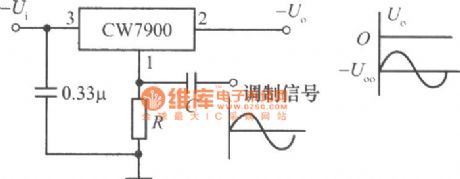
The power modulator circuit made by CW7900
Published:2011/9/26 21:21:00 Author:Rebekka | Keyword: Power modulator
View full Circuit Diagram | Comments | Reading(768)
Electric fan natural wind control circuit diagram
Published:2011/9/26 1:11:00 Author:Rebekka | Keyword: Electric fan, natural wind control

The nucleus of electric fan natural wind control circuit is an indirect feedback astable multivibrator. The circuir is composed of time-base integrated circuit and PTC thermistor, NTC thermistor.
Indirest feedback type astable multivibrator circuit.
2.5.2 The main device choice.
The fan natural wind autoregulate circuit uses RT1 NTC thermistor with B value in 5600K. Room temperature resistor is 51KΩ; RT2's room temperature is20~30℃, temperature coefficient is 12%/℃, room temperature resistance is 470KΩ. C should choose good insulation and small leakage current Tantalum electrolytic capacitor. CD6, VD7 choose small reverse current switch diode. The choice of VS is decided by the power of the electric fan. It is available for the 60W below fan.
(View)
View full Circuit Diagram | Comments | Reading(1845)
The remote control circuit diagram made of singlechip
Published:2011/9/14 22:43:00 Author:Rebekka | Keyword: remote control , singlechip

View full Circuit Diagram | Comments | Reading(1202)
Storage and Ni-MH Batteries Automatic Charger Circuit Diagram
Published:2011/9/14 22:43:00 Author:Rebekka | Keyword: Storage , Ni-MH Batteries , Automatic Charger

Batteries, Ni-MH battery automatic battery charger circuit, nickel hydrogen batteries, rechargeable battery are widely used in daily life, but often because of improper charge, the battery dies prematurely.
Properties: 1. The charger has a pulse current limiting charge, trickle charge and other functions in order to achieve intelligent charge without human care.2. The charger is triggered by battery power. There is no voltage output without connecting the battery; only the battery is connected correctly, the charge current will output. It has short circuit protection or reverse protection.3. The circuit has awide application. It performs in: ⑴ Wide input voltage range; ⑵ As long as you adjust the potentiometer, it will be suitable for other types of rechargeable batteries. (View)
View full Circuit Diagram | Comments | Reading(4844)
LED mains supply indicating circuit diagram
Published:2011/8/3 2:34:00 Author:Ecco | Keyword: LED , mains supply indicating

C1 and C2 in the circuit play the role of ballast and buck, andR is used for obstructing the transient inrush current. The circuit has low power consumption, reliable advantages, and it is suitable for electronic equipment as the instructions for mains supply.
(View)
View full Circuit Diagram | Comments | Reading(1740)
The sound circuit diagram of electronic lark
Published:2011/8/3 2:34:00 Author:Ecco | Keyword: sound circuit , electronic lark

The electronic bird circuit can emit fluctuated and different birds sound in different light, especially in the changing neon light irradiation, and its sound is constantly changing. The circuit is shown as the chart.
(View)
View full Circuit Diagram | Comments | Reading(2661)
Microphone amplifier circuit diagram
Published:2011/8/3 2:33:00 Author:Ecco | Keyword: Microphone amplifier

View full Circuit Diagram | Comments | Reading(778)
In-phase composite DC amplifier circuit diagram
Published:2011/9/19 1:16:00 Author:Ecco | Keyword: In-phase , composite DC amplifier

It uses the four operational amplifier 774 to achieve its parallel work, andit can drive 500Ω loads with goodlinear in the ± 10V range.
(View)
View full Circuit Diagram | Comments | Reading(841)
The driver circuit diagram of the voltage LED
Published:2011/8/3 2:35:00 Author:Ecco | Keyword: driver circuit, voltage LED

Voltage LED is convenient to use, but we should pay attention to the drive circuit's forms and ensure that the positive and negative tubes may not reversed; it must be used at rated voltage. Figure 1 shows four typical driven modes for reference.
(View)
View full Circuit Diagram | Comments | Reading(884)
The fuse fusing instruction circuit diagram
Published:2011/8/3 2:35:00 Author:Ecco | Keyword: fuse fusing instruction

The fuse fusing instruction circuit is shown in Figure 1, and it is very simple. Figure (a) shows the immediate light indicator circuit after fusing; figure (b) shows the instructions circuit, which can flash after fusing; figure (c) shows the circuit, which can issue the sound and light; figure (d) shows the circuit, in which the neon tube issues ligh before fusing and flashes after fusing.
(View)
View full Circuit Diagram | Comments | Reading(730)
TWH8778 power driver switch integrated circuit diagram
Published:2011/8/2 1:20:00 Author:Ecco | Keyword: power , driver , switch , integrated circuit
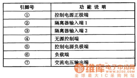

TWH8778 is a power driver switch IC, which is a common component used in many areas of the trigger-driven switch. 1. Features of functionsTWH8778 IC is made by FET and bipolar transistors using hybrid technology, it has the features of low static power consumption and high gain characteristics. The internal circuitincludes short circuit, overvoltage, overheating and other protection circuits, it also can work under poor environment and load conditions, it is small and easy to install. 2. Pin function TWH8778 IC uses single pin package, the pin functions are listed in Table. TWH8778 IC pin function 3. The typical application circuit The factory automatical control switch typical application circuit composed of TWH8778 integrated circuit is shown as the chart. The typical application circuit of TWH8778 integrated circuit
(View)
View full Circuit Diagram | Comments | Reading(1163)
| Pages:462/2234 At 20461462463464465466467468469470471472473474475476477478479480Under 20 |
Circuit Categories
power supply circuit
Amplifier Circuit
Basic Circuit
LED and Light Circuit
Sensor Circuit
Signal Processing
Electrical Equipment Circuit
Control Circuit
Remote Control Circuit
A/D-D/A Converter Circuit
Audio Circuit
Measuring and Test Circuit
Communication Circuit
Computer-Related Circuit
555 Circuit
Automotive Circuit
Repairing Circuit