Circuit Diagram
Index 266
3 Digit Display Scoreboard
Published:2012/11/21 2:11:00 Author:muriel | Keyword: 3 Digit, Display, Scoreboard
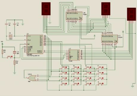
A few months ago Milardo starting to study the 8051 Microcontroller. From his research Miardo has designed a new circuit and called it 3-Digit Display Scoreboard with 4x4 Keypad Matrix . (View)
View full Circuit Diagram | Comments | Reading(3623)
PC Output Interface
Published:2012/11/21 2:10:00 Author:muriel | Keyword: PC , Output Interface
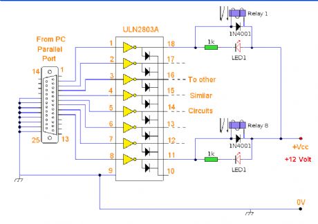
A versaile output interface that can control external devices direct from your computer. Uses freely available software and works with both windows and Linux. (View)
View full Circuit Diagram | Comments | Reading(745)
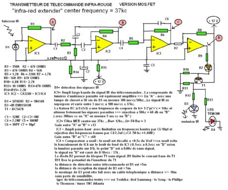
Infra Red Extender
Published:2012/11/21 2:09:00 Author:muriel | Keyword: Infra Red, Extender
View full Circuit Diagram | Comments | Reading(600)
A Passive Ethernet Hub
Published:2012/11/21 2:08:00 Author:muriel | Keyword: Passive Ethernet Hub
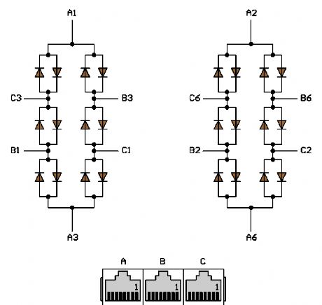
I tested this concept on a little network consisting of three PCs running under Windows 2000. It works well. The network adapters are normal Intel and 3Com models, set to 10 Mbps and Half Duplex. The computers are labelled A, B, C, and the UTP cables from the computers to the hub are 10, 16 and 35 meters long, respectively. (View)
View full Circuit Diagram | Comments | Reading(1756)
Curtain Control Circuit
Published:2012/11/21 2:07:00 Author:muriel | Keyword: Curtain, Control Circuit

This hybrid circuit uses a mixture of transistors, an IC and a relay and is used to automatically open or close a pair of curtains. Using switch S3 also allows manual control, allowing for curtains to be left only partially open or closed. The circuit controls a motor which is attached to a simple pulley mechanism, to move the curtains. I first started this circuit over 20 years ago and apart from now using metal gears, very little has changed. (View)
View full Circuit Diagram | Comments | Reading(1220)
R5000 Computer Interface
Published:2012/11/21 2:06:00 Author:muriel | Keyword: R5000 , Computer Interface

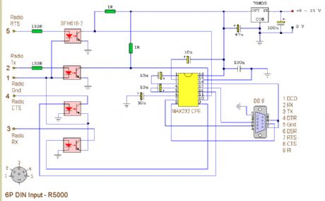
This circuit is a modified version of an original interface on QSL Net. It is a fully isolated interface allowing computer control of the Trio/Kenwood R5000 receiver. Separate software is needed to control the receiver. (View)
View full Circuit Diagram | Comments | Reading(1692)
IR Remote Control Modulation Detector
Published:2012/11/21 2:05:00 Author:muriel | Keyword: IR, Remote Control , Modulation Detector
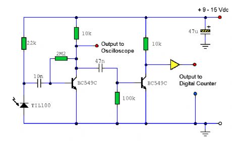
A circuit to extract and measure the modulated carrier of an Infra Red remote control. Note that the circuit does not physically separate control pulses from modulation, but amplifies the completereceived signal allowing the waveform to be displayed ideally on an oscilloscope or a frequency counter. Modulation frequencies between 1kHz and several MHz may be measured. (View)
View full Circuit Diagram | Comments | Reading(1395)
Infra Red Link
Published:2012/11/21 2:04:00 Author:muriel | Keyword: Infra Red, Link
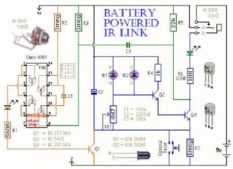
This is a battery powered IR Link which may be used in more than one room. The standby current is extremely low - giving a good battery life; and by shutting down in the presence of extraneous IR radiation it copes with the problem of excessive output current. (View)
View full Circuit Diagram | Comments | Reading(875)
Model rocket launch controller
Published:2012/11/21 2:02:00 Author:muriel | Keyword: Model rocket , launch controller


Most commercial rocket controllers available to buy are either expensive or do not have many features. After a lot of searching I found nothing that met my needs. I wanted a controller that could work multiple pads, as well as being easy to set up and pack away, so I designed my own. It has the ability to control up to 8 pads through a 6 core cable. You may want to be able to disconnect all your units. I used 6 pin DIN plugs so that all the units can be disconnected and easily transported. I wont go into details of how this works yet, although it is very useful as this type of cable is used in alarm systems and can be purchased cheaply. Each pad unit has a two sockets for signal input and output, with the input to the first pad unit coming from the controller. Any other units are then daisy chained to the first pad box. The controller also has a built in launch countdown controller, although this does have a bypass switch to use the controller in normal mode. On my controller I also added an accessory socket so that a large display can be connected to display the countdown sequence, although this is not included on the schematic to simplify the circuit. The main controller can also contain a rechargeable battery, although this does not have to be included. Not all features of my controller are shown on the circuit diagram, although you can easily add your own to suit your needs. (View)
View full Circuit Diagram | Comments | Reading(1278)
Infra Red Switch
Published:2012/11/21 2:00:00 Author:muriel | Keyword: Infra Red, Switch

This is a single channel (on / off) universal switch that may be used with any Infra Red remote control using 36-38kHz. (This is a very common remote handset frequency). In place of IR1 a TSOP1738 receiver may be used. (View)
View full Circuit Diagram | Comments | Reading(816)
Multi Rocket Launcher
Published:2012/11/21 1:58:00 Author:muriel | Keyword: Multi, Rocket Launcher

This launch controller can be used with low voltage battery igniters, which fire rocket engines in model rockets such as the Estes range. These circuits are electrical, only switches and contacts are involved. (View)
View full Circuit Diagram | Comments | Reading(611)
Infra Red Extender Mark 5
Published:2012/11/21 1:55:00 Author:muriel | Keyword: Infra , Red , Extender
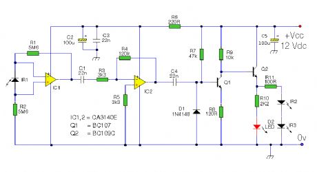
The latest addition to my collection of Infra Red (IR) Repeater circuits. The Mark 5 is a much improved version of the Mark 1 circuit and has increased range and sensitivity. It is also immune to the effects ofambient light, daylight and other forms of interference. In addition it works with IR modulation freuencies in the range 30 to 120kHz making the Mk5 circuit the best choice for compatibility with remote controls. (View)
View full Circuit Diagram | Comments | Reading(1047)
Infra Red Extender Mark 4
Published:2012/11/21 1:54:00 Author:muriel | Keyword: Infra, Red, Extender
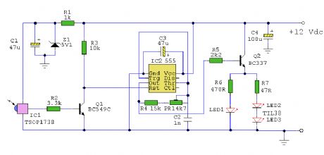
An Infra Red wired Repeater circuit to control appliances from a remote location. (View)
View full Circuit Diagram | Comments | Reading(746)
IR Remote Control Extender Mark 3
Published:2012/11/21 1:54:00 Author:muriel | Keyword: IR, Remote Control, Extender
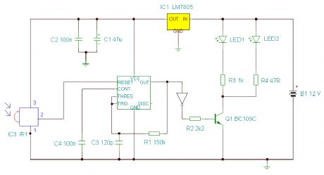
This Mark3 version of the Infra Red extender is a special version designed to control appliances that use high frequency modulated IR remote controls. (View)
View full Circuit Diagram | Comments | Reading(983)
IR Remote Control Extender Mark 2
Published:2012/11/21 1:53:00 Author:muriel | Keyword: IR , Remote Control, Extender
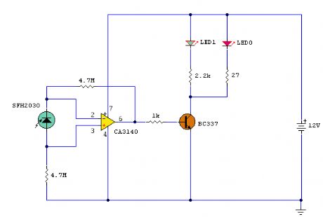
This is an improved IR remote control extender circuit. It has high noise immunity, is resistant to ambient and reflected light and has an increased range from remote control to the extender circuit of about 7 meters. It should work with any domestic apparatus that use 36-38kHz for the IR carrier frequency. Please note that this is NOT compatible with some satellite receivers that use 115KHz as a carrier frequency. (View)
View full Circuit Diagram | Comments | Reading(880)
Infra Red Remote Control Extender
Published:2012/11/21 1:52:00 Author:muriel | Keyword: Infra , Red , Remote Control, Extender
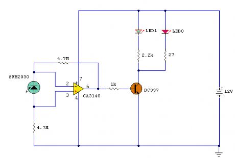
This circuit is used to relay signals from an Infra Red remote control in one room to an IR controlled appliance in another room. (View)
View full Circuit Diagram | Comments | Reading(629)
Loudness Control
Published:2012/11/21 1:49:00 Author:muriel | Keyword: Loudness Control
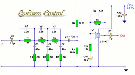
When listening to music at low volume levels, bass and treble frequencies are attenuated more than mid frequencies. This loudness control alters the frequency response curve to correspond roughly with the equal loudness characteristic of the ear. The circuit shown, is for a single channel, so for a stereo system, two such units should be built. This circuit has a boost of 13dB at 20Hz and approximately 9dB at 20kHz. (View)
View full Circuit Diagram | Comments | Reading(2166)
25 Watt Power Amplifier
Published:2012/11/21 1:49:00 Author:muriel | Keyword: 25 Watt , Power Amplifier
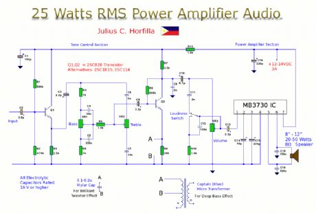
This is a 25 Watt power amplifier complete with separate preamp and tone controls. In addition the circuit has a loudness control (to boost bass at low audio power) and options for super bass and super treble enhancement. This is ideal for Ipod's, MP3 or CD players or can be used as a booster amplifier. (View)
View full Circuit Diagram | Comments | Reading(1773)
Audio Preamp
Published:2012/11/21 1:48:00 Author:muriel | Keyword: Audio Preamp

A 2 stage audio pre-amplifier with very good performance. (View)
View full Circuit Diagram | Comments | Reading(1423)
12 Volt 5 Watt Amplifier
Published:2012/11/21 1:47:00 Author:muriel | Keyword: 12 Volt , 5 Watt, Amplifier

This solid state amplifier uses 10 transistors and 5 diodes. It can deliver 5 Watts into a 4 ohm loudspeaker and about 3 Watts into an 8 ohm loudspeaker. It is made using Chineese transistors from the 1970's and 1980's. (View)
View full Circuit Diagram | Comments | Reading(2506)
| Pages:266/2234 At 20261262263264265266267268269270271272273274275276277278279280Under 20 |
Circuit Categories
power supply circuit
Amplifier Circuit
Basic Circuit
LED and Light Circuit
Sensor Circuit
Signal Processing
Electrical Equipment Circuit
Control Circuit
Remote Control Circuit
A/D-D/A Converter Circuit
Audio Circuit
Measuring and Test Circuit
Communication Circuit
Computer-Related Circuit
555 Circuit
Automotive Circuit
Repairing Circuit
