
Circuit Diagram
Index 278
1-W Linear FM Booster
Published:2012/11/11 20:06:00 Author:muriel | Keyword: 1-W, Linear, FM, Booster

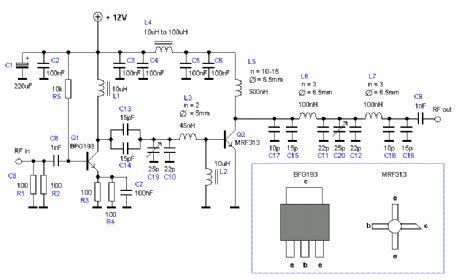
This RF Amplifier is used for boosting small fm transmiters and bugs. It use two Philips 2N4427 and its power is about 1Watt. At the output you can drive any linear with BGY133 or BLY87 and so on. Its power supply has to give 500mA current at 12 Volts. More voltage can boost the distance but the transistors will be burned much earlier than usual.! In any case do not exceed the 15Volts. The Amp offers 15 dB in the area of 80Mhz to 110 Mhz. L4, L5, and L6 are 5mm diameter air coils, 8 turns, with wire 1mm wire diameter.An easy project, with great results. (View)
View full Circuit Diagram | Comments | Reading(1565)
1W FM Transmitter
Published:2012/11/11 20:03:00 Author:muriel | Keyword: 1W, FM , Transmitter
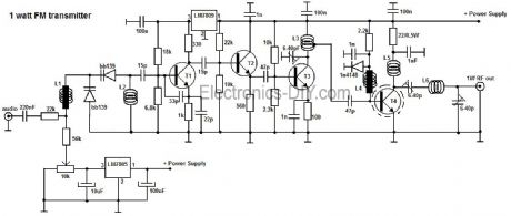
A very good 1 watt fm transmitter circuit, very easy to build circuit. It has 4 transistors, one is a very stable oscillator, followed by a buffer stage to prevent frequency variation when you adjust the transmitter. Next is a resonance stage and the final stage built with a minimum 1W transistor which must have a heatsink. You must use a LM7805 stabilizer for the oscillator diodes and one LM7809 for powering up the T1 oscillator stage. This will give you a very stable transmitter frequency.
First build the oscillator stage and the buffer, power it up and trim the 10k linear potentiometer untill you can here a blank signal on your receiver. If you put a small piece of wire on the T2 emitter you can see that the cover range of the 2 stage transmitter is about 3 meter. After you are sure that your oscillator+buffer stage are working properly, remove the power supply and continue building the T3 resonance stage. Connect the power supply and if you adjust the trimmer (variable capacitor) from T3 collector you can see how the fm transmitter power can be varied. This stage is very important for proper functionality of the entire 1 watt fm transmitter. You must adjust the trimmer for maximum power. 1 Watt fm transmitter adjustment The final stage of the 1W fm transmitter is built with 2N4427 (recommended) or the transistors from the list. If you can抰 find any, use a BD139 transistor but only for frequencies lower than 90 MHz. The output power will be lower but you get the idea. If you decide to use 2N2219 transistor for the final stage of the transmitter you must know that the output rf power will be 0.4W. Adjust the last 2 trimmers for maximum output power in the antenna. Initially use 2 x 100 Ω 0.5W resistors in parallel at the RF output. Then connect this rf probe to the output and adjust all the 3 trimmers starting from T3 to output. You must adjust it to obtain the maximum multimeter indication. Then power it off, connect the antenna and make the final adjustments for maximum broadcasting coverage distance. The oscillator and buffer stage must be enclosed in a 1 mm copper case, then do the same with the T3 and T4 stages. Use a 12Vdc power supply to power up this fm broadcast circuit. T4 will have a current consumption of around 150 mA at full power output adjustments. The total current consumption of the entire 1 watt transmitter will be around 500 mA.
(View)
View full Circuit Diagram | Comments | Reading(940)
1KM Power FM Transmitter
Published:2012/11/11 20:02:00 Author:muriel | Keyword: 1KM, Power , FM, Transmitter
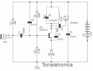
This small power FM transmitter can transmit more than 1 km in good conditions. The modulation can be made so much with a microphone or audio source. Circuit of power fm transmitter is built around 2n2218 transistor. Transmitter coil is 5 turns of enameled 22 AWG wire, with diameter of 1 cm without nucleus. Look at the capacitors that it should be ceramic. The antenna should possess from 15 to 40 cm. For transmission it ties a receiver of FM (radio) in the proximity to half volume in a free frequency (that there is not any radio operating), with a wood or plastic key, rotate the screw of CV to capture the frequency of the transmitter. (View)
View full Circuit Diagram | Comments | Reading(2168)
1GHZ Frequency Meter
Published:2012/11/11 20:00:00 Author:muriel | Keyword: 1GHZ , Frequency , Meter

This is 1GHz frequency counter with 100KHz resolution. Meter is built in around PIC16F84A microcontroller and SAB6456 / U813BS prescaller. (View)
View full Circuit Diagram | Comments | Reading(4070)
15dB UHF TV Antenna Booster
Published:2012/11/11 19:58:00 Author:muriel | Keyword: 15dB , UHF, TV Antenna , Booster

This is an UHF band TV antenna preamplifier circuit With 15dB gain to build easily. It is formed based on BF180 UHF Transistor. The first stage is an band pass filter constructed by the C1, CV1, L1, L4, C7 and C3, the second stage is a base-common voltage amplifier with low input impedance to match. Build the L1 ~ L4 as air core coil to obtain high Q-Factor. After assembling, pack it into a proper metallic box and connect the ground of the circuit to the box to reduce noise effect. (View)
View full Circuit Diagram | Comments | Reading(1505)
100W Transmitter RF Power Amplifier 2SC2782
Published:2012/11/11 19:57:00 Author:muriel | Keyword: 100W , Transmitter , RF, Power Amplifier, 2SC2782
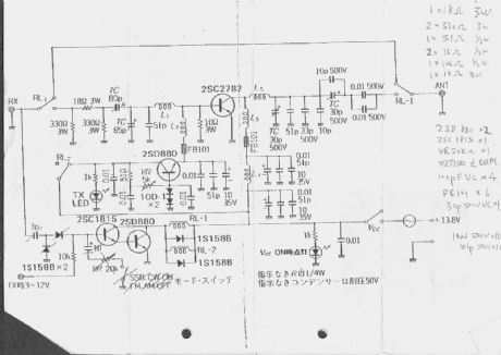
This is a 6m band transmitter RF power amplifier (50 MHz) with 100W output. It used with my FT-736R and drive from 10W for the 6m SSB DX. The Building information comes from Japan CQ Magazine. The Toshiba RF bipolar power transistor is used in it. If you want to construct this rf amplifier, it's the better way if the double side PCB use for increase the grounding and current transfer. The TX power can be tune to 120W. (View)
View full Circuit Diagram | Comments | Reading(3358)
100W Transmitter Amplifier for 2200m
Published:2012/11/11 19:56:00 Author:muriel | Keyword: 100W , Transmitter, Amplifier, 2200m
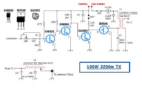
This particular transmitter was later shipped up to VY1JA in the Yukon where, thanks to Jay's excellent antenna system, it was heard in Europe as well as in New Zealand during one of the Trans-Pacific Tests! Running 24 volts on the final will produce 100 watts into a 50 ohm load. The transmitter utilizes a 4060 binary counter IC chip as both the crystal oscillator and frequency divider. I used a 2200 kHz crystal along with the 'divide-by' sixteen output to produce a signal at 137.5 kHz. Other combinations of crystal frequencies and 'divide-by' combinations may also be used since the 4060 features divided outputs for f/32 (pin 5) and f/64 (pin 4), among others. You may have a 4MHz crystal or an 8MHz crystal in your junk box that will put you in the band using these output pins.
I used a crystal oven from a very old taxi cab fm radio to mount the crystal but do not use the 'oven' feature. I discovered that the thermostat-controlled heating / cooling cycle produced more drift than simply leaving the oven off. I have however, lined both the inside and the outside of the oven with styrofoam in hopes of keeping the crystal's temperature change to a minimum. Initial tests indicate that it is entirely adequate for QRSS30 speeds. I have not yet tested it at QRSS60, where even the slightest drift shows up very quickly. The transmitter is simple and inexpensive to construct. The IRF540 FET final runs very cool, although it should probably be heat sinked. I have also used IRF640s with little or no change noted. All coils and transformers are wound on ABS or PVC tubing. TRANSMITTER SCHEMATIC I used the Manhattan Style of construction on pc board. TRANSMITTER PCB Output Transformer (T1) - wound on 1.5 tubing ~ 5 inches in length. Wind the secondary first which consists of 80 turns of ~ #20 enamel wire. Wind the primary centered on top of the secondary with 15 turns of ~ #16 enamel, close spaced. Before winding the primary, wrap the center part of the secondary with PVC electrical tape or heavy plumber's teflon tape. Output Filter (L1) - wound on 2 tubing ~ 5 inches in length. Wrap 80 turns of #20, close spaced with taps at 40 turns and every 5 turns until the end. The capacitor used at the drain of the FET should be of high quality such as polycarbonate or mica. Although the original design indicated a 1 uF capacitor at the top end of T1's primary, I found that the 2.2uf gave a better waveform across the FET's drain. Look for the typical class-e type waveform at the drain. CLASS-E WAVEFORM Operation - Mitch's version of this amp appears to be operating at greater efficiency than the one I built. Running the final at 24VDC, the FET draws around 6.5-7 amps for an input of approximately 160W. With a measured output of 95W, the efficiency is around 60%. A properly designed class-e amplifier should realize much higher efficiencies so there is still plenty of room for improvement on this design. One of the things I would like to do is experiment with the output transformer in order to optimize its performance. Perhaps rewinding it on a ferrite core would help. The output transformer develops a lot of heat, indicating a substantial power waste. Perhaps that is where the missing 30% efficiency can be reclaimed. Operate the transmitter into a 50 ohm dummy load or your resonant (50 ohm) antenna system. You might want to 'tune-up' at a lower voltage and then increase the drain voltage when adjustments are completed. Start with the antenna tapped at the coaxial end of the filter coil. As you tap closer to the center, power output will increase, as will final amplifier drain current. You will reach a point where the output does not increase any further, even though drain current has increased. Tap at the point of best efficiency. The output waveform should be a clean sine-wave. (View)
View full Circuit Diagram | Comments | Reading(3170)
1.5W VHF Amplifier
Published:2012/11/9 21:05:00 Author:muriel | Keyword: 1.5W , VHF Amplifier
This project will explain the basic function of a class-C transmitter. I will explain how to dimension a transmitter and the purpose of the different components. I will also explain how you can build a 1.5W PA transmitter. The project will include PCB, components and instructions how to make coils, assembly and testing. (View)
View full Circuit Diagram | Comments | Reading(3049)
1.5V Tracking Transmitter
Published:2012/11/9 21:05:00 Author:muriel | Keyword: 1.5V , Tracking Transmitter
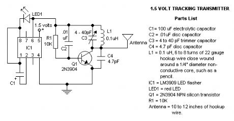
With this circuit you can build a very small tracking transmitter that can be tracked using a FM broadcast band radio receiver. The transmitter can be powered from any 1.5V volt battery or power supply. Transmitter has a range up to 1 mile depending on battery voltage, height above ground, receiver sensitivity, and antenna length. Under certain conditions distances of 1 mile have been achieved. It is recommended that this transmitter be used with FM radios that can tune continuously across the dial. The better the receiver and receiver antenna system the greater the practical range of the transmitter, however good functionality can be achieved with the least expensive radios and using only the standard telescoping antenna included with most radios.
Additional Notes o For stability, use a NPO types for C2 & C4. o Resistance tolerance for R1 should be 1 or 2%. o Frequency range is the usual 87-109Mhz on the FM dial. o The coil is made from 22 ga 'hookup' wire, like the solid Bell phone wire. Leave the insulation on. o The LED is the 'High Brightness' type for maximum illumination, although this type will draw more current. 87.6Mhz full view The current draw for this tracker is 3.7mA, so the 1.5V button cell will last a while. My experimental version was tuned to 87.6MHz and worked as expected on only 1.5 volts. The photo shows I just glued the whole thing on a 1.5V AA battery. The led glows at the same oscillation as the beat-frequency What the heck am I suppose to hear you ask? When your circuit is working you should see the LED flash quite fast. Take your FM radio and search for the low-beat 'thumpe-thumpe-thumpe-etc' equal to the flash of the LED (probably around the 100Mhz). Found it? If that position is interfering with a radio station you can fine-tune it with the variable capacitor. If you like to have the tracker around the 88Mhz (or lower) you can do that by keeping the windings from the home-made coil close together. Anyways, play with it and learn. It may take a lot of patience to find the signal but once you know where it is it becomes simple. It is a nice learning project. The 12-inch antenna can be anything, it is not really that critical. I used a piece of 22 gauge flexible wire.
(View)
View full Circuit Diagram | Comments | Reading(1213)
1.5-V FM Broadcast Transmitter
Published:2012/11/9 21:04:00 Author:muriel | Keyword: 1.5-V, FM , Broadcast, Transmitter
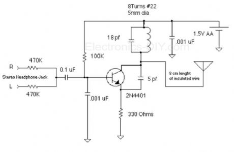
The objective of this 1.5V FM Broadcast Transmitter design is to provide a simple low-power transmitter solution for broadcasting audio from various audio sources. This transmitter accepts stereo input via two 470K resistors. Since there is no audio level control on the input, the audio level out from the source needs to be adjusted. Or, you can just add a 10k as an input level control. Transmitter's frequency, as built is tunable via spreading or compressing the coil to the desired frequency, and the coil can be glued down. If you want to make one that's tunable, it might be easiest to reduce the 18 pf capacitor and put a small trimmer capacitor in parallel with the inductor (across the reduced value capacitor). Voltage variable capacitors would be an nice alternative to a mechanical variable capacitor but they don't offer much tuning range with only a 1.5V power supply.
Notice: Before operating a radio transmitter, find out what kind of transmitter operation, if any, is permitted in your locality. Radio transmitter operation is a serious legal matter. In the United States, operation of unlicensed intentional radiators is covered by Part 15 of Title 47 of the Code of Federal Regulations. This design can be readily adapted to different frequencies and different power levels. If you choose to build and operate the transmitter described here, you do so at your own risk. I'm only publishing this as an example of what can be done. This implementation is adapted to rebroadcast the output of a CD player, television receiver, or radio receiver. I use it so that I can move about the house and listen to my favorite programs without disturbing others. Within and the house, I find that I can get 10 to 20 meters away from the transmitter with the small pocket FM receiver I carry in my shirt pocket. Your mileage may vary. The transmitter as built and pictured below (the transmitter is in the blob of hot melt glue on the end of the battery holder) does not have an on-off switch. I put a 1.5 AA cell that was run down too far to run my CD player in this transmitter and it ran for over a month before I replaced it. The one in the transmitter at this moment has been running it continuously for over three months. Current draw is only about a milliamp with a new battery (assuming you don't have a super-high beta transistor in which case the theoretical limit is about 2.5 ma). An on-off swich is not necessary, though it may satisfy an emotional need. Tips to get it working: Wind the coil on a 4 or 5 mm diameter Philips blade screwdriver or similar form then slip it off. I used some vinyl insulated #24 hookup wire as well as #30 enameled wire. In both cases, I played with the length of the coil to tune the transmitter to a dead spot on the FM band. The coil is held in place with hot melt glue. If you don't have a spectrum analyzer or frequency meter, use a good-quality FM receiver to make sure its tuned where you think it is. While adjusting the coil, keep in mind that all superheterodyne receivers have images. If you find that two or more adjustments make the transmitter show up on the same spot on the receiver, it might be necessary to take a short walk and find out which adjustment drops out first -this would be the image, because the receiver's front end (if it has a tuned front end) will reduce its sensitivity to the image. Many kinds of transistors will work fine in this application. After all, its only an oscillator (frequency modulation is obtained my modulating the base-collector voltage, thereby modulating the depth of the depletion layer of the reverse-biased base-collector junction, which results in a change in capacitance at the collector, which results in a change the resonant frequency of the collector circuit.). I used an 2N4401 because I have a lot of them. I like 2N3904 and MPSH34 for this too.
(View)
View full Circuit Diagram | Comments | Reading(1155)
1.5V Battery Operated Rebroadcast FM Transmitter
Published:2012/11/9 21:03:00 Author:muriel | Keyword: 1.5V, Battery, Operated Rebroadcast, FM, Transmitter
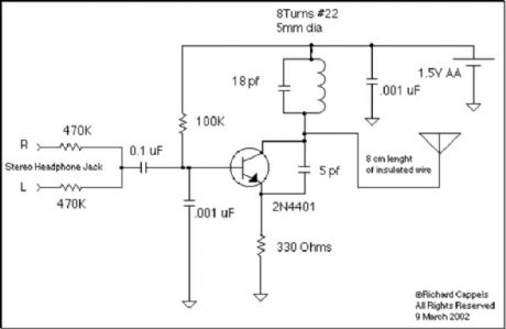
This implementation is adapted to rebroadcast the output of a CD player, television receiver, or radio receiver. I use it so that I can move about the house and listen to my favorite programs without disturbing others. Within and the house, I find that I can get 10 to 20 meters away from the transmitter with the small pocket FM receiver I carry in my shirt pocket. Your mileage may vary. The transmitter as built and pictured below (the transmitter is in the blob of hot melt glue on the end of the battery holder) does not have an on-off switch. I put a 1.5 AA cell that was run down too far to run my CD player in this transmitter and it ran for over a month before I replaced it. The one in the transmitter at this moment has been running it continuously for over three months. Current draw is only about a milliamp with a new battery (assuming you don't have a super-high beta transistor in which case the theoretical limit is about 2.5 ma). An on-off swich is not necessary, though it may satisfy an emotional need.
Tips to get it working: Wind the coil on a 4 or 5 mm diameter Philips blade screwdriver or similar form then slip it off. I used some vinyl insulated #24 hookup wire as well as #30 enameled wire. In both cases, I played with the length of the coil to tune the transmitter to a dead spot on the FM band. The coil is held in place with hot melt glue. If you don't have a spectrum analyzer or frequency meter, use a good-quality FM receiver to make sure its tuned where you think it is. While adjusting the coil, keep in mind that all superheterodyne receivers have images. If you find that two or more adjustments make the transmitter show up on the same spot on the receiver, it might be necessary to take a short walk and find out which adjustment drops out first -this would be the image, because the receiver's front end (if it has a tuned front end) will reduce its sensitivity to the image. Many kinds of transistors will work fine in this application. After all, its only an oscillator (frequency modulation is obtained my modulating the base-collector voltage, thereby modulating the depth of the depletion layer of the reverse-biased base-collector junction, which results in a change in capacitance at the collector, which results in a change the resonant frequency of the collector circuit.). I used an 2N4401 because I have a lot of them. I like 2N3904 and MPSH34 for this too. . Variations The objective of this design is to provide a simple, appliance-like low-power transmitter to rebroadcast audio. This transmitter does not have pre-emphesies, so it is not high-fidelity. It has sort of an AM sound for music and is fine for speech. Since there is no audio level control on the input, the audio level out of the CD player (or whatever you are driving it with) needs to be adjusted. Or, you can just add a 10k to 50k as an input level control, its no big deal. This transmitter, as built is not tunable once assembled, the coil tweaked to the desired frequency, and everything glued down. If you want to make one that's tunable, it might be easiest to reduce the 18 pf capacitor and put a small trimmer capacitor in parallel with the inductor (across the reduced value capacitor). Voltage variable capacitors would be an nice alternative to a mechanical variable capacitor but they don't offer much tuning range with only a 1.5V power supply. Notice: Before operating a radio transmitter, find out what kind of transmitter operation, if any, is permitted in your locality. Radio transmitter operation is a serious legal matter. In the United States, operation of unlicensed intentional radiators is covered by Part 15 of Title 47 of the Code of Federal Regulations. This design can be readily adapted to different frequencies and different power levels. If you choose to build and operate the transmitter described here, you do so at your own risk. I'm only publishing this as an example of what can be done.
(View)
View full Circuit Diagram | Comments | Reading(1661)
1.5-Watt FM Transmitter
Published:2012/11/9 21:02:00 Author:muriel | Keyword: 1.5-Watt, FM, Transmitter
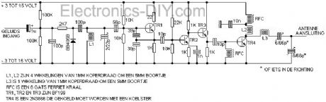
Presented here is a 1.5 Watt FM Transmitter. A transmitter is an installation in which electrical oscillations are generated by an antenna as radio waves are emitted.Although there are a variety of channels exist in terms of size, application and frequency, each transmitter is an oscillator is present (usually crystal controlled) that an electric thrill, the carrier, with a constant frequency electricity.This is followed by one or more selective amplifier stages tuned oscillation circuits, which usually frequency multiplication is performed.Modulation can occur at low power, and even strengthening of the modulated signal to the power required to reach.Modulation can also occur at high power, when the carrier signal and separately reinforced.
The oscillator, Step 1 consists of no less than three universal RF transistors: the BF199.These together provide enough power to the buffer, Step 2 to drive.If the buffer transistor is in a 2N3866 which is able to deliver even 1.8 watts.This gives you only if you have the full voltage of the transistor on it.In any case, make sure you cool it well with a koelster.Wij usually use 12 or 13.8 volt power supplies.Power from an old PC to work well here because they usually already well shielded, cooled and stabilized. Schematic of 1.5 watt FM transmitter: Please note that the need for an antenna, a piece of coax or a dummy load to the antenna output to connect.If you do not turn on the transmitter and then it is extremely likely that the 2N3866 burns.
(View)
View full Circuit Diagram | Comments | Reading(1687)
1.3W VHF RF Amplifier 2SC1970 88-108 MHz
Published:2012/11/9 21:01:00 Author:muriel | Keyword: 1.3W, VHF, RF Amplifier, 2SC1970, 88-108 MHz
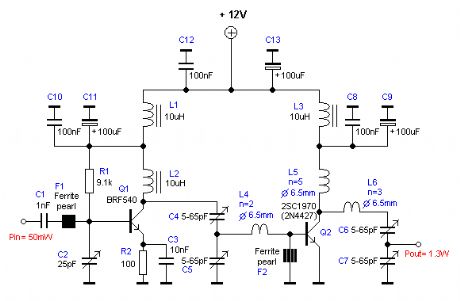
This RF power amplifier is based on the transistor 2SC1970 and 2N4427. The output power is about 1.3W and the input driving power is 30-50mW. It will still get your RF signal quit far and I advice you to use a good 50 ohm resistor as dummy load. To tune this amplifier you can either use a power meter/wattmeter, SWR unit or you can do using a RF field meter.
RF Amplifier Assembly Good grounding is very important in a RF system. I use bottom layer as Ground and I connect it with the top with wires to get a good grounding. Make sure you have some cooling at the transistor. In my case I put the 2SC1970 close to the PCB to handle the heat. With good tuning the transistor shouldn't become hot. RF Amplifier Printed Circuit Board You can download a pdf file which is the black PCB. The PCB is mirrored because the printed side side should be faced down the board during UV exposure. To the right you will find a pic showing the assembly of all components on the same board. This is how the real board should look when you are going to solder the components. It is a board made for surface mounted components, so the copper is on the top layer. I am sure you can still use hole mounted components as well. Grey area is copper and each component is draw in different colors all to make it easy to identify for you. The scale of the pdf is 1:1 and the picture at right is magnified with 4 times. Click on the pic to enlarge it. Low-Pass Filter Some of you might want to add a low-pass filter at the output. I have not added any extra low pass filter in my construction because I don't think it is needed. You can easy find several homepages about low pass filter and how to build them.
(View)
View full Circuit Diagram | Comments | Reading(2685)
1 Watt Universal RF Amplifier
Published:2012/11/9 20:59:00 Author:muriel | Keyword: 1 Watt , Universal, RF Amplifier

View full Circuit Diagram | Comments | Reading(1823)
1 Watt QRP Power Transmitter
Published:2012/11/9 20:58:00 Author:muriel | Keyword: 1 Watt , QRP , Power Transmitter

The 1 watt 20 meter QRP transmitter with VXO. This is a nice QRP transmitter that can be used in combination of one of the simple receivers. Normally these designs have only two transistors: one is the X-tal oscillator and the second the final amplifier. A good example is my first QRP rig that is also described somewhere on this site. Here the VXO (Variabele X-tal Oscillator) has a tuning range of 16 kHz. This VXO is buffered with an extra driver stage for a better frequency stability and a varicap diode is used instead of a variabele capacitor. An extra transistor is added for keying the transmitter with a low keying current. What you can do with such a simple 1 watt QRP power transmitter. This is a real low power transmitter, so do not expect that you can do everything with it but... When conditions are normal, you can easily make many QSO's during one afternoon with stations with distances upto 2000 km with a simple inverted V wire dipole antenna! From Europe, I did even make QSO's across the Ocean! (View)
View full Circuit Diagram | Comments | Reading(1200)
1-Watt Four Stage FM Transmitter
Published:2012/11/9 20:57:00 Author:muriel | Keyword: 1-Watt , Four Stage, FM , Transmitter

This FM transmitter circuit uses four radio frequency stages: a VHF oscillator built around transistor BF494 (T1), a preamplifier built around transistor BF200 (T2), a driver built around transistor 2N2219 (T3) and a power amplifier built around transistor 2N3866 (T4). A condenser microphone is connected at the input of the oscillator.
Working of the 1 Watt transmitter circuit is simple. When you speak near the microphone, frequency-modulated signals are obtained at the collector of oscillator transistor T1. The FM signals are amplified by the VHF preamplifier and the pre-driver stage. You can also use transistor 2N5109 in place of 2N2219. The preamplifier is a tuned class-A RF amplifier and the driver is a class-C amplifier. Signals are finally fed to the class-C RF power amplifier, which delivers RF power to a 50-ohm horizontal dipole or ground plane antenna. Use a heat-sink with transistor 2N3866 for heat dissipation (Note: or 2N4427 because it works better at 12 V and delivers up to 1 watt RF power). Carefully adjust trimmer VC1 connected across L1 to generate frequency within 88-108 MHz. Also adjust trimmers VC2 through VC7 to get maximum output at maximum range. Regulator IC 78C09 provides stable 9V supply to the oscillator, so variation in the supply voltage will not affect the frequency generated. You can also use a 12V battery to power the circuit. Assemble the circuit on a general purpose PCB. Install the antenna properly for maximum range. Coils L1 through L5 are made with 20 SWG copper-enameled wire wound over air-cores having 8mm diameter. They have 4, 6, 6, 5 and 7 turns of wire, respectively. (View)
View full Circuit Diagram | Comments | Reading(0)
0.1 - 3.5GHz Prescaler-2
Published:2012/11/9 20:52:00 Author:muriel | Keyword: 0.1 - 3.5GHz, Prescaler

This handy prescaler divides input frequency by 1000. It takes maximum input frequency of 3.5GHz and converts it into 3.5MHz that may be measured using standard frequency meter. (View)
View full Circuit Diagram | Comments | Reading(1433)
0.1 - 3.5GHz Prescaler
Published:2012/11/9 20:50:00 Author:muriel | Keyword: 0.1 - 3.5GHz, Prescaler

View full Circuit Diagram | Comments | Reading(1301)
LCD RF Power meter, AD8307 sensor schematic
Published:2012/11/9 20:49:00 Author:muriel | Keyword: LCD, RF, Power meter, AD8307 , sensor schematic

View full Circuit Diagram | Comments | Reading(5258)
0-500MHz PIC16F876 RF Power Meter
Published:2012/11/9 20:48:00 Author:muriel | Keyword: 0-500MHz, PIC16F876 , RF, Power Meter
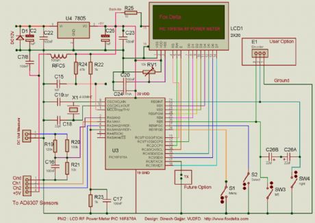
RF Measurement has been an expensive work so far the cost of measuring instruments are concerned. RF Meter is based on PIC16F876 microcontroller, AD8307 and 2x20 LCD display. Full documentation is included. (View)
View full Circuit Diagram | Comments | Reading(4251)
| Pages:278/2234 At 20261262263264265266267268269270271272273274275276277278279280Under 20 |
Circuit Categories
power supply circuit
Amplifier Circuit
Basic Circuit
LED and Light Circuit
Sensor Circuit
Signal Processing
Electrical Equipment Circuit
Control Circuit
Remote Control Circuit
A/D-D/A Converter Circuit
Audio Circuit
Measuring and Test Circuit
Communication Circuit
Computer-Related Circuit
555 Circuit
Automotive Circuit
Repairing Circuit