
Circuit Diagram
Index 272
USB Mono FM Transmitter
Published:2012/11/15 20:57:00 Author:muriel | Keyword: USB, Mono, FM, Transmitter

This small FM transmitter with a range of about 50 meters designed for connection to the USB port. With lots of mini-transmitters then you have a comprehensive, action-packed radio program. Due to the power supply via the USB port of a high frequency stability is achieved. Alternatively, the receiver, a battery 5 to 12 volts to operate.
FM Transmitter Construction USB FM Transmitter Prototype It is not necessary to drill the transmitter PCB. All components will be soldered to the plate with their legs folded, like this: The two transistors and the LEDs are polarized: The transistor has a flat side, the LED a foot longer than the other is the anode (A), the other is the cathode (K). The audio cable (minijack) must be transformed from a stereo cable into a cable. Mono Sound: Soldering together the white and red cables, leaving aside the yellow cable (mass). The frequency setting will be turning the variable capacitor gently with a screwdriver or thin cardboard but rigid. FM Transmitter Parts List 1 Ohm resistor 510 (green � brown � brown) 100 resistor 1 kOhm (brown � black � yellow) 1 MOhm resistors (brown � black � green) 1 capacitor 0.1 uF (0.1) 1 nF capacitor 47 (0.047) 1 capacitor 4.7 pF (479) 2 pF capacitors 22 (22) 1 variable capacitor 1.5 pF � 15 2 transistor BF 246 (F246A) 1 red LED 1 audio cable (minijack) (View)
View full Circuit Diagram | Comments | Reading(3042)
USB FM Transmitter MAX2606
Published:2012/11/15 20:56:00 Author:muriel | Keyword: USB , FM , Transmitter , MAX2606

This MP3 Player FM transmitter can be used to listen to your own music throughout your home. The transmitter circuit use no coils that have to be wound. When this FM transmitter used in the car, there is no need for a separate input to the car stereo to play back the music files from your MP3 player. (View)
View full Circuit Diagram | Comments | Reading(1733)
USB FM Transmitter
Published:2012/11/15 20:55:00 Author:muriel | Keyword: USB , FM, Transmitter

Here is a simple USB FM transmitter that could be used to play audio files from an MP3 player or computer on a standard VHF FM radio by connecting it to an USB port. The circuit use no coils that have to be wound. This USB transmitter can be used to listen to your own music throughout your home. To keep the fm transmitter circuit simple as well as compact, it was decided to use a chip made by Maxim Integrated Products, the MAX2606. This IC from the MAX2605-MAX2609 series has been specifically designed for low-noise RF applications with a fixed frequency. The VCO (Voltage Controlled Oscillator) in this IC uses a Colpitts oscillator circuit. The variable-capacitance (varicap) diode and feedback capacitors for the tuning have also been integrated on this chip, so that you only need an external inductor to fix the central oscillator frequency. (View)
View full Circuit Diagram | Comments | Reading(1536)
UHF-TV Preamplifier2
Published:2012/11/15 20:54:00 Author:muriel | Keyword: UHF-TV , Preamplifier

View full Circuit Diagram | Comments | Reading(1934)
UHF-TV Preamplifier
Published:2012/11/15 20:53:00 Author:muriel | Keyword: UHF-TV, Preamplifier

View full Circuit Diagram | Comments | Reading(0)
TV Video Transmitter
Published:2012/11/15 20:51:00 Author:muriel | Keyword: TV , Video, Transmitter

This is a TV transmitter for transmitting video of various video sources such as video cameras, Satellite receivers, DVD players, game consoles, etc. TV transmitter's circuit is working on the 470-580 MHz frequency and can be received on UHF channels 21-34. TV Video transmitter can radiate as far as 300 meters by using a 10-20 cm wire antenna. TV transmitter requires voltage of 9-15 Volts. However, you can also use a 9v batteries. Oscillator is based around BF199 and BFR90 RF transistors. If needed the range of TV transmitter can be extended by replacing BFR90 with 2N3886 transistors. (View)
View full Circuit Diagram | Comments | Reading(2301)
TV Transmitter Circuit2
Published:2012/11/15 20:50:00 Author:muriel | Keyword: TV, Transmitter Circuit

This is a small TV transmitter circuit which transmits in VHF band, negative sound modulation and PAL video modulation. It is suitable in countries where the B and G system is used. (View)
View full Circuit Diagram | Comments | Reading(1126)
TV transmitter circuit
Published:2012/11/15 20:49:00 Author:muriel | Keyword: TV , transmitter circuit

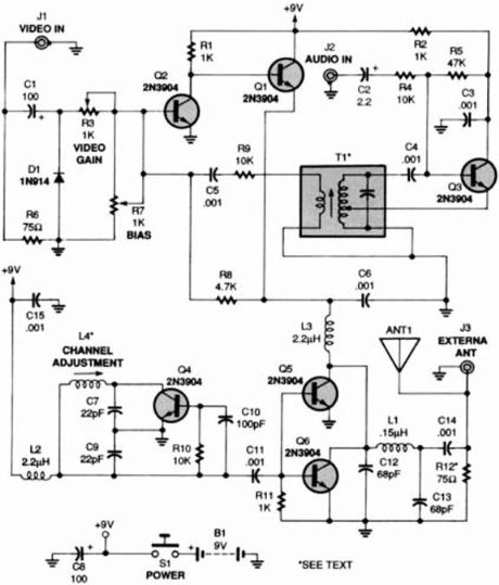
The TV transmitter given here uses UK standard 1 FM modulation for sound and PAL for video modulation. The audio signal to be modulated is pre-amplified using the transistor Q1 and associated components. The transistor Q2 has two jobs: production of carrier frequency and modulation. The pre-amplified audio signal is fed to the base of transistor Q2 for modulation. Capacitor C5 and inductor L1 forms the tank circuit which is responsible for producing the carrier frequency. The video signal is fed to the emitter of transistor Q2 via POT R7 for modulation. The modulated composite signal (audio+video) is transmitted by the antenna A1.
Notes: Assemble the circuit on a good quality PCB. Inductor L1 can be made by making 4 turns of 24SWG enameled copper wire on a 6mm dia: plastic former. T1 can be a radio frequency transformer with built in capacitor. (Can be found on old transistor radio boards). Antenna A1 can be a 1M long copper wire. (Experiment with the length to get optimum performance). This transmitter is working in VHF band somewhat between 50 � 210MHz. This transmitter is compatible only with PAL B and PAL G systems. (View)
View full Circuit Diagram | Comments | Reading(1808)
TV Transmitter2
Published:2012/11/15 20:48:00 Author:muriel | Keyword: TV, Transmitter
One of the most useful gadgets a video enthusiast can have is a low-power TV Transmitter. Such a device can transmit a signal from a VCR to any TV in a home or backyard. Imagine the convenience of being able to sit by the pool watching your favorite movie on a portable with a tape or laser disc playing indoors. You could even retransmit cable TV for your own private viewing. (View)
View full Circuit Diagram | Comments | Reading(1041)
TV Transmitter
Published:2012/11/15 20:48:00 Author:muriel | Keyword: TV, Transmitter

A VHF band TV transmitter using negative sound modulation and PAL video modulation. This is suitable for countries using TV systems B and G. (View)
View full Circuit Diagram | Comments | Reading(1677)
TV Audio Video Transmitter
Published:2012/11/15 20:47:00 Author:muriel | Keyword: TV , Audio , Video, Transmitter

This TV transmitter transmits audio and video signal from Camcoder Camera, DVD, VHS, Satellite, video game, etc. Playing them in a channel free from the strip of VHF. These signal can be radiated with a common antenna and captured in an it distances of until about 500 meters that it is the most appropriate for urban areas, reminding that and necessary to be a lot of caution and careful for not interfering in frequencies of other issuing, as well as to emergency services. Depending on the local conditions (existence or not of obstacles). Fed with tensions from 12 to 15 Volts, the circuit has excellent I carry out so much in the emission of monochrome signal, as in colors. An important point of this project 倀he easiness with that he can be set up and adjusted, since only two coils are used. Ideal to be used with surveillance cameras turning the without thread. As it Works the tv video and audio transmitter with lm1889n The heart of this circuit transmitter 俰s the integrated circuit LM1889N of National Semiconductor, that consists of a Modulator of Video for TV in an involucres of 18 pins DIL. (View)
View full Circuit Diagram | Comments | Reading(2065)
Telephone FM Transmitter
Published:2012/11/15 20:46:00 Author:muriel | Keyword: Telephone, FM , Transmitter

This FM transmitter attaches in series to one of your phone lines. When there is a signal on the line (that is, when you pick up the handset) the circuit will transmit the conversation. In particular it will radiate from the phone line itself. It is a passive device - there is no battery. It uses the signal on the phone line for power. No aerial is needed - it feeds back the RF signal into the phone line which radiates it in the FM band. The frequency of transmission may be adjusted by the trimcap. (View)
View full Circuit Diagram | Comments | Reading(967)
Stereo FM Transmitter circuit with BA1404
Published:2012/11/15 20:45:00 Author:muriel | Keyword: Stereo , FM , Transmitter , BA1404
With this Stereo FM Transmitter with BA1404 you will be able to create a mini stereo FM station and broadcast to your entire home, a simple way to have an audio link wireless with ease. With the FM transmitter BA1404 Hifi Stereo you can stream your music from your iPod MP3, satellite receiver, computer, DVD player, Mobile Phone, MP4 player and MP3 and other audio source directly to an FM receiver with crystal clear sound. (View)
View full Circuit Diagram | Comments | Reading(5722)
Stereo FM Transmitters with BA1404
Published:2012/11/15 20:43:00 Author:muriel | Keyword: Stereo , FM, Transmitters, BA1404

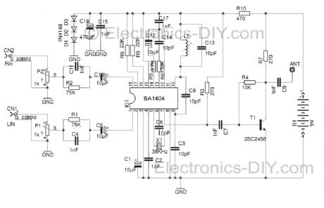
A high quality stereo FM transmitter circuit is shown here. The circuit is based on the IC BA1404 from ROHM Semiconductors. BA1404 is a monolithic FM stereo modulator that has built in stereo modulator, FM modulator and RF amplifier. The FM modulator can be operated from 76 to 108MHz and power supply for the circuit can be anything between 1.25 to 3 volts. In the circuit R7, C16, C14 and R6, C15, C13 forms the pre-emphasis network for the right and left channels respectively. This is done for matching the frequency response of the FM transmitter with the FM receiver. Inductor L1 and capacitor C5 is used to set the oscillator frequency. Network C9,C10, R4,R5 improves the channel separation. 38kHz crystal X1 is connected between pins 5 and 6 of the IC. Composite stereo signal is created by the stereo modulator circuit using the 38kHz quartz controlled frequency.
Assemble the circuit on a good quality PCB. Powering the circuit from a battery will reduce noise. Use an 80 cm copper wire as antenna. For L1 make 3.5 turns of 0.5mm dia enamelled copper wire on a 5mm dia ferrite core.
(View)
View full Circuit Diagram | Comments | Reading(1128)
Stereo FM Transmitter with BA1404
Published:2012/11/15 20:42:00 Author:muriel | Keyword: Stereo , FM, Transmitter , BA1404

Circuit of stereo FM transmitter of of high quality using integrated circuit ba1404 for mp3, mp4, ipod, computer, radio of the car. Transmit of your equipment of portable audio for the radio of your car, transmitters of fm of low potency are the ideal for transmission wireless of audio sign for fm receivers. Mainly in that case that is treated of transmitter of FM stereo with ba1404. The heart of that circuit is the circuit integrated ba1404, that is a mini fm transmitter, that already counts with the necessary internal circuits for transmission in fm. just being necessary to increase some components discman or any other audio source turning the wireless. If you already set up other transmitters of transistorized fm it will see that when setting up that with having integrated BA1404, that the quality of the sound and the frequency stability is excellent. Besides the but it presents easy assembly. (View)
View full Circuit Diagram | Comments | Reading(2870)
Stereo FM Transmitter Using BA1404
Published:2012/11/15 20:40:00 Author:muriel | Keyword: Stereo , FM , Transmitter, BA1404

A high quality stereo FM transmitter circuit is shown here. The circuit is based on the IC BA1404 from ROHM Semiconductors. BA1404 is a monolithic FM stereo modulator that has built in stereo modulator, FM modulator, RF amplifier circuitry. BA1404 FM transmitter can be operated from 76 to 108MHz and power supply for the circuit can be anything between 1.25 to 3 volts.
In the circuit R7, C16, C14 and R6, C15, C13 forms the pre-emphasis network for the right and left channels respectively. This is done for matching the frequency response of the FM transmitter with the FM receiver. Inductor L1 and capacitor C5 is used to set the oscillator frequency. Network C9,C10, R4,R5 improves the channel separation. 38kHz crystal X1 is connected between pins 5 and 6 of the IC. Composite stereo signal is created by the stereo modulator circuit using the 38kHz quartz controlled frequency. (View)
View full Circuit Diagram | Comments | Reading(2346)
Spy FM Transmitter Bug
Published:2012/11/15 20:40:00 Author:muriel | Keyword: Spy , FM , Transmitter Bug

Here's a tiny one transistor spy FM transmitter bug that operates from a single 1.5V AA battery. Main advantage of this circuit is that power supply is a 1.5 Volts cell (any size) which makes it possible to fix PCB and the battery into very tight places. Transmitter even runs with standard NiCd rechargeable cells, for example a 750mAh AA size battery runs it about 500 hours (while it draws 1.4mA at 1.24V) which equals to 20 days. This way circuit especially valuable in amateur spy operations. Mini FM transmitters take place as one of the standard circuit types in an amateur electronics fan's beginning steps. When done right, they provide very clear wireless sound transmission through an ordinary FM radio over a remarkable distance. I've seen lots of designs through the years, some of them were so simple, some of them were powerful, some of them were hard to build etc. (View)
View full Circuit Diagram | Comments | Reading(1336)
Simple RF Power Meter
Published:2012/11/15 1:01:00 Author:muriel | Keyword: Simple , RF , Power Meter
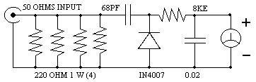
Here is a simple set up which will enable them to measure the out put power of their transmitter. All that they require is a good multimeter which has a sensitivity of 20k ohms/4 Watts which is adequate for low power transmitters. Many beginners trying out their skill with QRP TX, for the first time have to overcome many problems before they are able to come on the air. On usual complaint is that, every thing is working fine but the signal is not going out.
The 8k resistor should be kept close to the out put terminal of the transmitter. Switch on the transmitter in the CW mode and measure the DC voltage with the multimeter. If the voltage is V then the out put power is given by Power = V^2/50
(View)
View full Circuit Diagram | Comments | Reading(2420)
Simple FM Transmitter Bug
Published:2012/11/15 1:01:00 Author:muriel | Keyword: Simple , FM , Transmitter Bug

This is a simple design of a small FM Transmitter Bug that's perfect for transmitting and eavesdropping purposes. Due to the high sensitivity, even the ticking of the clock to hear. The range is estimated at anything from 50 meters. With a small piece of wire as an antenna to get at least the whole house. L1 and L2 are two equal air pools. They each consist of 5 turns at a diameter of about 4 mm. The thickness of the wire does not matter, 0.5 mm works perfectly. C4 is the frequency adjustment. Tune an FM radio in an empty area of the FM band and C4 to turn your silence or hear a whistle. From what you can precisely adjust the radio and the transmitter installed in a room somewhere to intercept. Note: Because these transmitter bugs inherently unstable, you better read the short legs of the components keep the circuit mechanically tightly together up. Also placing a 1 nF capacitor (C6) will benefit stability. R1, R3, R4: 4K7 R2: 100K R5: 10K R6: 270 Ohms C1, C2: 10 uF C3, C6: 1 nF C4: 2-18 pF trimmer C5: 5.6 pF L1, L2: air puddle windings on May 4 mm in diameter (see text) T1, T2: 547 BC Condenser microphone Original Text: Ook het plaatsen van een 1 nF condensatortje (C6) over de voedingsaanluitingen komt de werking ten goede. (View)
View full Circuit Diagram | Comments | Reading(2031)
Simple FM Transmitter circuit
Published:2012/11/15 1:00:00 Author:muriel | Keyword: Simple , FM, Transmitter circuit

Mini FM transmitters take place as one of the standard circuit types in an amateur electronics fan's beginning steps. When done right, they provide very clear wireless sound transmission through an ordinary FM radio over a remarkable distance. I've seen lots of designs through the years, some of them were so simple, some of them were powerful, some of them were hard to build etc. Here is the last step of this evolution, the most stable, smallest, problem-less, and energy saving champion of this race. Circuit given below will serve as a durable and versatile FM transmitter till you break or crush it's PCB. Frequency is determined by a parallel L-C resonance circuit and shifts very slow as battery drains out. (View)
View full Circuit Diagram | Comments | Reading(1162)
| Pages:272/2234 At 20261262263264265266267268269270271272273274275276277278279280Under 20 |
Circuit Categories
power supply circuit
Amplifier Circuit
Basic Circuit
LED and Light Circuit
Sensor Circuit
Signal Processing
Electrical Equipment Circuit
Control Circuit
Remote Control Circuit
A/D-D/A Converter Circuit
Audio Circuit
Measuring and Test Circuit
Communication Circuit
Computer-Related Circuit
555 Circuit
Automotive Circuit
Repairing Circuit