
Circuit Diagram
Index 276
5 Watt Transmitter
Published:2012/11/13 21:47:00 Author:muriel | Keyword: 5 Watt , Transmitter
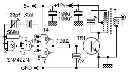
This is a very simple 5 watt CW TX based upon a TTL logic chip. There is just one tricky component and this is Cx. This component should have an impedance of about 10 - 50 ohms at the frequency of interest. If you wish to reduce the transmitter power, increase the value of Cx. It is Cx which causes the square wave from the output transistor to approximate a sine waveform. The value of Cx is the price of simplicity in this TX. (View)
View full Circuit Diagram | Comments | Reading(1412)
5 Watt FM Amplifier
Published:2012/11/13 21:47:00 Author:muriel | Keyword: 5 Watt, FM , Amplifier
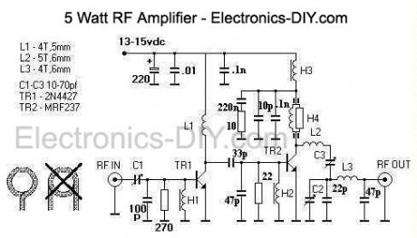
This design is a 2 stage amplifier that has about 17db of gain, suitable for an input of 50 to 100 MW. Its basically a Veronica 5 watt vco transmitter, without the vco. The transistors are a 2N4427 and a MRF237. Output power is 2.5 to 5 watts, depending on input drive and dc voltage. At 13.7 vdc with 50 MW of drive, the output was 2.5 watts. The maximum dc voltage recommended is about 15-16 volts.
The unit is constructed with copper clad board, a large piece is used as the construction surface and is mounted into a case. Other board material is cut into small pads, then glued to the construction surface for part connections. A heatsink is needed for the both transistors, a small top hat style will work for TR1 but TR2 requires a larger heatsink thats attached to the case. This is made from aluminum L stock, a 3/8 hole and a slot is made for TR2 to fit snuggly in. Up to 7-8 watts output is possible with this amp, but for continious duty only 5 watts maximum output is recommended. A fan is required and it is mouted on the case lid, with holes drilled for ventilation. The chokes H1, H2 and H3 are 5 turns of 30 awg wire on a ferite bead and choke H4 is a 330 ohm 1/2 watt resistor with 14 turns of 30 awg with a ferite bead on each end. Ferite beads need to be of type 43 material. The coils L1, L2 and L3 are made of 18 awg tinned wire. A 1.5 amp 3ag fuse is part of the dc power cord assembly. I used BNC coax connectors for input and output, however SO-239 or F type connectors would be fine too. Tune up and use: In order to make the amplifier operate properly, it needs to be tuned. To start, set all the trimmer capacitors to middle position, connect the rf out to a wattmeter/dummy antenna, apply power and drive from the exciter then tune for maximum output. Limit your drive to 100 MW maximum. If you can measure the amplifier transistor's current, then adjust for minimum current at maximum rf out. This unit has no swr protection and requires a 50 ohm antenna, do not operate the amplifier without a proper load.
(View)
View full Circuit Diagram | Comments | Reading(3749)
Phase sequence indicator circuit using incandescent and capacitor
Published:2012/11/13 19:55:00 Author:Ecco | Keyword: Phase sequence, indicator , incandescent , capacitor

Some devices do not allow the motor reverses, when you install phase sequence identification, the motor wiring is required to be correct. Phase sequence indicator shown in the figure is easy to make, firstly, you can use the insulating handle Alligator Clip to hold a phase of power as the starting phase L1. Another two insulated handle Alligator Clips must touch the other two phases of power supply, then you can identify power supply phase sequence by two bulbs' brightness difference.
(View)
View full Circuit Diagram | Comments | Reading(5138)
Multi-function electric fan control circuit with crickets sound using PT2124
Published:2012/11/13 20:13:00 Author:Ecco | Keyword: Multi-function , electric fan , control circuit , crickets sound

As shown in the figure, when you press speed key to start the fan, in each case, it is operates with stroke. M-end (15 feet) outputs drive signal which is added to VT1 (PNP tube)'s b pole by R6 to make VT1 get conduction, e pole's low level signal can triggers IC2. IC2 uses animal voice simulation integrated circuit KD-56020, once it is triggered, the animal voice is broadcasted as signal which is amplified by Darlington-level with VT2 and VT3-l, then it drivies speakers b to emit sound.
(View)
View full Circuit Diagram | Comments | Reading(979)
Simulated natural wind fan control circuit accompanied by the waves sound
Published:2012/11/13 20:25:00 Author:Ecco | Keyword: Simulated natural wind, fan control, waves sound

It consists of a variable frequency multivibrator, relay control circuit, analog waves sound circuit and AC buck rectifier circuit. Ordinary fan is configurated with the control circuit which can allow wind to be strong or weak and accompanied by realistic sound of the waves. People will have natural feelings when they are enjoying the cool wind. VT1, VT2, C1, C2, R1~R3 and RP1 form a multivibrator.
(View)
View full Circuit Diagram | Comments | Reading(775)
The speed control circuit without governor
Published:2012/11/13 20:34:00 Author:Ecco | Keyword: speed control , without governor
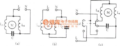
General capacitor start motor circuit is shown in (a), it uses capacitor phase shift to produce starting torque. If the motor winding connection is changed into series from parallel, as shown in Figure ( b ), at this time, the voltage of the main winding LR and the secondary winding LA is relatively lower than the parallel, it is equivalent of connecting a reactor in series in the circuit, then the motor speed natural declines.
(View)
View full Circuit Diagram | Comments | Reading(790)
Automatically input control circuit of the pump station preparedness
Published:2012/11/13 20:38:00 Author:Ecco | Keyword: Automatically input, control , pump station preparedness

Plant cooling water pump house often needs to configure multiple pumps and equipment units ( one of them is used as standby pump ). When one pump stops due to a fault, standby pump will be automatically prepared and put into operation, and the number of pumps is decided by the amount of water.
(View)
View full Circuit Diagram | Comments | Reading(1415)
JK1-125 auto buck starter circuit
Published:2012/11/12 19:43:00 Author:Ecco | Keyword: auto buck starter

In the figure, WJ is the energy saving and silent running device, you can use it to save energy and reduce noise.
(View)
View full Circuit Diagram | Comments | Reading(1224)
EOCR motor protection circuit
Published:2012/11/12 20:27:00 Author:Ecco | Keyword: EOCR , motor protection


EOCR is Korea SAMWHA 's new motor protector with a microprocessor, , there are two popular kinds of EOCR-SS type EOCR-3DD in the market. Wiring diagram is shown in Figure 2.
(View)
View full Circuit Diagram | Comments | Reading(2445)
The motor overheating and influent protection circuit
Published:2012/11/12 20:39:00 Author:Ecco | Keyword: motor , overheating , influent protection

Before the burned-out motor damage, its winding temperature rises high; in many occasions, motor is easily bilging, resulting in burned. The circuit is shown in Figure. It can prevent overheating influent accidents. RT is a positive temperature coefficient thermistor (PTC); M, N are plastic insulated wires which are closed and buried in the motor stator windings, and their heads are stripped, they are used for detecting the motor inlet.
(View)
View full Circuit Diagram | Comments | Reading(3354)
Capacitor start single-phase motor non- frequent commutation circuit
Published:2012/11/12 20:50:00 Author:Ecco | Keyword: Capacitor start, single-phase motor, non- frequent commutation
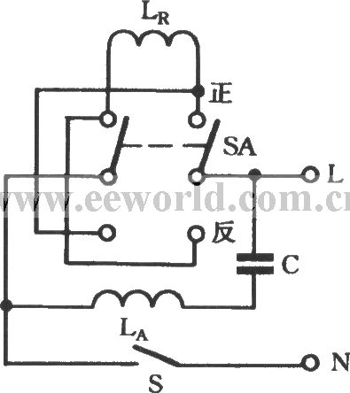
The resistance of motor's main winding LR and secondary winding LA is not equal, if it is measured with a multimeter, the winding without connecting to a capacitor C in series with smaller resistance is the main winding LR; the winding connected to capacitor C in series with larger resistance is the secondary winding LR. The working principle is shown in Fig. C is the secondary winding starting capacitor, it is typically 1μF, SA is a DPDT button switch KN3 -3 - 2 × 2.
(View)
View full Circuit Diagram | Comments | Reading(1154)
The Chunhua cleaner electronic speed control circuit
Published:2012/11/12 20:57:00 Author:Ecco | Keyword: Chunhua , cleaner , electronic , speed control

This circuit is composed of the following two parts: (1) phase shifting circuit. R1, RP, C2 constitute a phase shifting circuit. When the voltage VC2 across C2 gets the breakover voltage of trigger diode VD, VD gets conduction, C2 discharges, three-terminal bidirectional thyristor VS can control of pole flow pulse current is triggered by conduction. Adjusting potentiometer RP can adjust the phase of the gate pulse and change the conduction angle of VS, thereby adjusting the motor voltage and controlling the rotational speed of the M.
(View)
View full Circuit Diagram | Comments | Reading(1189)
Network intelligent control Tap (data Tap )
Published:2012/11/11 21:52:00 Author:Ecco | Keyword: Network, intelligent control Tap, data Tap
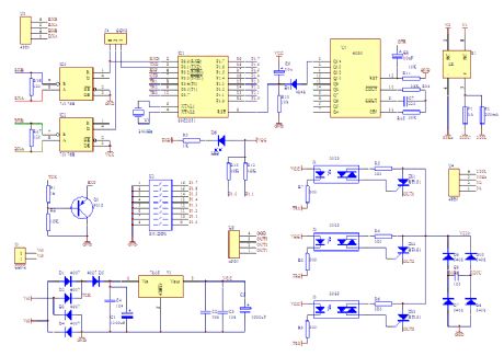
Network intelligent control Tap is shown as the figure:
(View)
View full Circuit Diagram | Comments | Reading(706)
The PLL synthesized oscillator circuit diagram
Published:2012/11/11 20:16:00 Author:Ecco | Keyword: PLL , synthesized oscillator

PLL synthesizer oscillator circuit is a feedback loop composed of reference oscillator, phase comparator, loop filter, voltage controlled oscillator, programmable frequency divider and other components. In the circuit, the reference oscillator uses a crystal oscillator (OSC) to output 1MHz or l00kHz 1/1000 or 1/100 divider and generate 1kHz signal, then it is compared with the output of 1 / N sub- frequency circuit. 4046 contains PC1 and PC2 two-phase comparators which can obtain the output corresponding to phase difference or frequency.
(View)
View full Circuit Diagram | Comments | Reading(5619)
The oscillator circuit diagram composed of crystal inverter
Published:2012/11/11 21:19:00 Author:Ecco | Keyword: oscillator , crystal inverter

In the circuit, crystal X ( 3.2MHz ) forms the oscillator circuit, after its oscillation output is connected to BCD counter CD4518, it will divide the original oscillation frequency, then the CD4518's different output ends can get the signals with different frequencies, If the terminal A outputs the l20kHz frequency signal, the terminal B outputs 24kHz frequency signal, the terminal C outputs 12kHz frequency signal.
(View)
View full Circuit Diagram | Comments | Reading(1511)
Wien bridge oscillator circuit diagram
Published:2012/11/11 21:42:00 Author:Ecco | Keyword: Wien bridge, oscillator

As shown in figure, when it generates low-frequency sine wave, usually it uses the capacitor and resistor to determine the oscillation frequency of RC oscillator circuit. There are many RC oscillator network circuits such as the the Wien bridge oscillator circuit, T-shaped bridge oscillator circuit, phase-shifting oscillator circuit. Figure 6-13 is a Wien bridge oscillator circuit exa,ple, and it is composed of op amp A1 and some capacitors and resistors elements, etc. , and it can obtain the the stable sine wave with the degree of distortion being below 1%.
(View)
View full Circuit Diagram | Comments | Reading(1828)
Triangle wave / square wave output voltage-controlled oscillator circuit diagram
Published:2012/11/11 20:08:00 Author:Ecco | Keyword: Triangle wave, square wave , output, voltage-controlled oscillator

The circuit is composed of the polarity switching circuit, inverting integrator and delay comparator. It uses VT1 switch for polarity switching, the amplifier A1 makes noninverting and inverting work alternately. For example, when VT1 gets conduction, A1 operates for an inverting amplifier. Integrator A2 can integrate the voltage gotten from polarity switching circuit in accordance with the R1 and C1, when points reach Delay comparator's reference voltage, the integrator will reverse and continuously repeat this operation.
(View)
View full Circuit Diagram | Comments | Reading(2474)
40mW FM TRANSMITTER
Published:2012/11/11 20:29:00 Author:muriel | Keyword: 40mW , FM TRANSMITTER
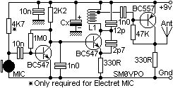
The transmitters on my homepage seem to be quite popular, especially those intended for the 88 - 108MHz FM band. I must really confess that I also favor this broadcast band, mainly because it is so easy to find signals on the workshop radio. Everyone has an FM radio, and it is fun to play with. Experimental antennas and the like can all be developed in this band since there are a huge range of beacons all transmitting just for my benefit :-). Basic oscillators also are easy to fault-find in this frequency band, and then later modified for other VHF bands. The V5 FM Wireless Microphone is a 10mW transmitter that featured a coil fabricated on the PCB itself. This made the project easy to duplicate and removed microphony (the ability of coils to act as a microphone with spring-line reverb). But as several people have already commented, although more stable than most other similar kits and projects, the frequency still does vary with battery voltage. In just one session it can vary by 200kHz when a cheap Mighty Atom battery falls to 8 volts. (View)
View full Circuit Diagram | Comments | Reading(732)
400mW VCO FM transmitter
Published:2012/11/11 20:28:00 Author:muriel | Keyword: 400mW , VCO FM, transmitter

With good antenna (dipole placed outdoor and high) the transmitter has very good coverage range about 500 meters, the maximal coverage range is up to 4 km. (View)
View full Circuit Diagram | Comments | Reading(1453)
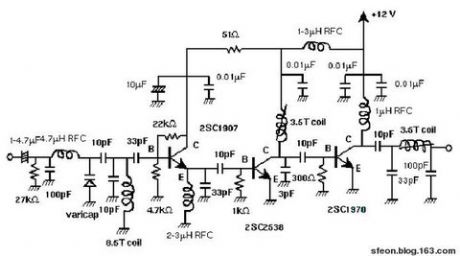
3W FM Transmitter Amplifier
Published:2012/11/11 20:27:00 Author:muriel | Keyword: 3W , FM Transmitter, Amplifier
View full Circuit Diagram | Comments | Reading(4195)
| Pages:276/2234 At 20261262263264265266267268269270271272273274275276277278279280Under 20 |
Circuit Categories
power supply circuit
Amplifier Circuit
Basic Circuit
LED and Light Circuit
Sensor Circuit
Signal Processing
Electrical Equipment Circuit
Control Circuit
Remote Control Circuit
A/D-D/A Converter Circuit
Audio Circuit
Measuring and Test Circuit
Communication Circuit
Computer-Related Circuit
555 Circuit
Automotive Circuit
Repairing Circuit