Amplifier Circuit
5 Watt FM Amplifier
Published:2012/11/13 21:47:00 Author:muriel | Keyword: 5 Watt, FM , Amplifier | From:SeekIC

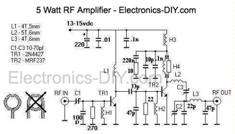
This design is a 2 stage amplifier that has about 17db of gain, suitable for an input of 50 to 100 MW. Its basically a Veronica 5 watt vco transmitter, without the vco. The transistors are a 2N4427 and a MRF237. Output power is 2.5 to 5 watts, depending on input drive and dc voltage. At 13.7 vdc with 50 MW of drive, the output was 2.5 watts. The maximum dc voltage recommended is about 15-16 volts.
The unit is constructed with copper clad board, a large piece is used as the construction surface and is mounted into a case. Other board material is cut into small pads, then glued to the construction surface for part connections. A heatsink is needed for the both transistors, a small top hat style will work for TR1 but TR2 requires a larger heatsink thats attached to the case. This is made from aluminum L stock, a 3/8 hole and a slot is made for TR2 to fit snuggly in. Up to 7-8 watts output is possible with this amp, but for continious duty only 5 watts maximum output is recommended. A fan is required and it is mouted on the case lid, with holes drilled for ventilation. The chokes H1, H2 and H3 are 5 turns of 30 awg wire on a ferite bead and choke H4 is a 330 ohm 1/2 watt resistor with 14 turns of 30 awg with a ferite bead on each end. Ferite beads need to be of type 43 material. The coils L1, L2 and L3 are made of 18 awg tinned wire. A 1.5 amp 3ag fuse is part of the dc power cord assembly. I used BNC coax connectors for input and output, however SO-239 or F type connectors would be fine too. Tune up and use: In order to make the amplifier operate properly, it needs to be tuned. To start, set all the trimmer capacitors to middle position, connect the rf out to a wattmeter/dummy antenna, apply power and drive from the exciter then tune for maximum output. Limit your drive to 100 MW maximum. If you can measure the amplifier transistor's current, then adjust for minimum current at maximum rf out. This unit has no swr protection and requires a 50 ohm antenna, do not operate the amplifier without a proper load.
Reprinted Url Of This Article:
http://www.seekic.com/circuit_diagram/Amplifier_Circuit/5_Watt_FM_Amplifier.html
Print this Page | Comments | Reading(3)

Article Categories
power supply circuit
Amplifier Circuit
Basic Circuit
LED and Light Circuit
Sensor Circuit
Signal Processing
Electrical Equipment Circuit
Control Circuit
Remote Control Circuit
A/D-D/A Converter Circuit
Audio Circuit
Measuring and Test Circuit
Communication Circuit
Computer-Related Circuit
555 Circuit
Automotive Circuit
Repairing Circuit
Code: