
power supply circuit
Index 129
LOW_COST_VOLTAGE_REGULATOR
Published:2009/7/20 21:24:00 Author:Jessie
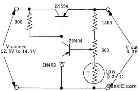
Costs 5 to 7 times less than toner regulator having same power rating. Can be set at precise voltage value required, whereas zener has 5 or 10% tolerance. Uses IN462 silicon diode for reference. Total cost (in quantity) is less than two dollars. Thermistor makes circuit perform from -55 to 71°C. Input voltage source is sea-water-activated batttery.-M. E. Gavin, Low Cost Transistor Voltage Regulator, EEE, 10:8, p 28-29.
(View)
View full Circuit Diagram | Comments | Reading(674)
BASIC_SERIES_PASS_REGULATOR
Published:2009/7/20 21:23:00 Author:Jessie
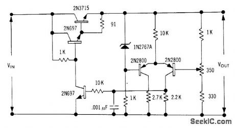
Output volt-age is regulated by 2N37l5 series-pass sill con power transistor having rise and fall limes below 0.5 microsec at 5 amp. Transistor has wide safe-area range, but circuit otherwise has no overload protection.-J. Takesuye and H. Weber, Silicon Power Transistors Provide New Solutions to Voltage Control Problems, Motorola Application Note AN-163, Aug. 1965. (View)
View full Circuit Diagram | Comments | Reading(884)
BALANCED_INPUT_PENIODE_TWIN_IRIODE
Published:2009/7/20 21:58:00 Author:Jessie

Balanced input stage reduces effects of tube aging and heater voltage change. Plate load of 16,500 ohms on output pentode contributes to excellent frequency response. Neither reference tube nor comparison voltage divider are loaded. Gives outstanding over-all performance.-NBS, Handbook Preferred Circuits Navy Aeronautical Electronic Equipment.” 1, Electron Tube Circuits, 1963,p N2-4. (View)
View full Circuit Diagram | Comments | Reading(1951)
TEMPERATURE_COMPENSATED_ZENER
Published:2009/7/20 21:56:00 Author:Jessie

Reference voltage is compared to 27-v output by dual-chip transistor serving as error amplifier. Unique end-compensation circuit using sensistor generates voltage that rises with temperature.-C. H. Moulton, Light Pulse System Shrinks High-Voltage Protection Device, Electronics, 38:11, p 71-75. (View)
View full Circuit Diagram | Comments | Reading(717)
NEGATIVE_OUTPUT_300_V_REGULATOR
Published:2009/7/20 21:54:00 Author:Jessie
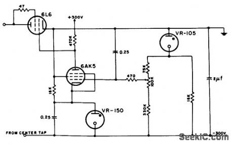
Operation is comparable to corresponding positive-output circuit.-NBS, Handbook Preferred Circuits Navy Aeronautical Electronic Equipment, Vol. 1, Electron Tube Circuits, 1963, p N2-5. (View)
View full Circuit Diagram | Comments | Reading(667)
NEGATIVE_OUTPUT_152_V_REGULATOR
Published:2009/7/20 21:53:00 Author:Jessie
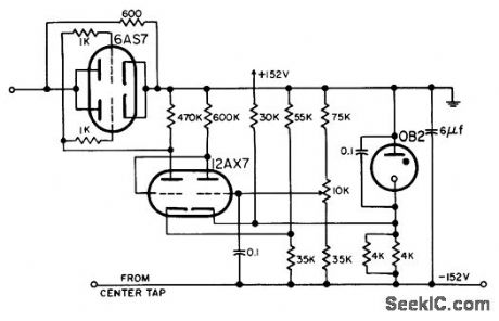
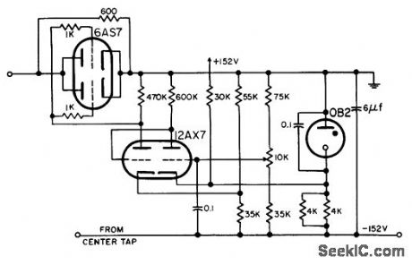
Operation is comparable to corresponding positive-output circuit.-NBS, Handbook Preferred Circuits Navy Aeronautical Electronic Equipment, Vol. 1, Electron Tube Circuits, 1963, p N2-5. (View)
View full Circuit Diagram | Comments | Reading(588)
DARLINGTON_TRANSISTOR_SERIES_REGULATOR
Published:2009/7/20 22:05:00 Author:Jessie

Integrated transistor and zener diode in reference amplifer act with 2N2795 Darlington transistor to hold 50-ma output to within less than 0.001% of 12 v over 10% variation in a-c line voltage.-T. P. Sylvan, New Device Simplifies Power Supply Design, Electronics, 36:20, p 39-43. (View)
View full Circuit Diagram | Comments | Reading(768)
REFERENCE_AMPLIFIER_TESTS_POWER_SUPPLY_STABILITY
Published:2009/7/20 22:03:00 Author:Jessie

Integrated transistor and tenor diode serve as reference amplifier for testing effects of temperature on output voltage. After amplifier is heated or cooled, voltage divider is adjusted to restore initial collector current, and change in reference voltage is read from voltage divider scale to within 1 my.-T. P. Sylvan, New Device Simplifies Power Supply Design, Electronics, 36:20, p 39-43. (View)
View full Circuit Diagram | Comments | Reading(496)
PENTODE_WITH_RIPPLE_SUPPRESSION
Published:2009/7/20 22:02:00 Author:Jessie
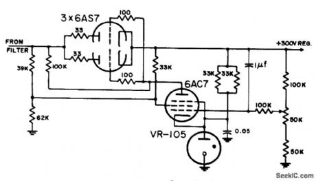
Screen is fed jointly from regulated and unregulated sides of supply, to reduce ripple. Plate load is low (100,000 ohms), providing good frequency response but increasing current fluctuations in VR-105.-NBS, Handbook Preferred Circuits Navy Aeronautical Electronic Equipment, Vol. 1, Electron Tube Circuits, 1963, p N2-2. (View)
View full Circuit Diagram | Comments | Reading(1405)
VOLTAGE_TUNABLE_MAGNETRON_FILAMENT_SUPPLY
Published:2009/7/20 22:00:00 Author:Jessie
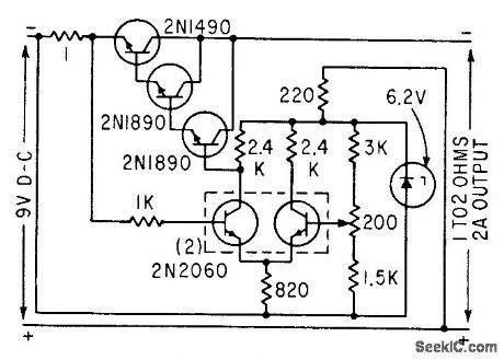
Voltage drop across 1-ohm resistor, proportional to output current, is compared with fixed reference and held constant by series pass element.-S. Prigozy, Designing Special Power Supplies for Voltage-Tunable Oscillators, Electronics, 35:44, p 48-50. (View)
View full Circuit Diagram | Comments | Reading(760)
SIMPLE_SERIES_REGULATOR
Published:2009/7/20 21:59:00 Author:Jessie
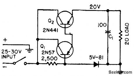

Satisfactory for power supplies that are not subjected to shorted, capacitive, or suddenly increased loads. Any capacitance C1 at load must be charged through Q2, so entire supply voltage appears across Q2 before C1 starts charging. If initial charging current exceeds limits of Q2, it will be damaged immediately or become unstable.-H. D. Ervin, Transistor Power Supply has Overload Protection, Electronics, 31:25, p 74-75. (View)
View full Circuit Diagram | Comments | Reading(899)
6_V_at_20_A
Published:2009/7/20 21:50:00 Author:Jessie

Constant-voltage ferrores-onant transformer with full-wave silicon rectifiers is supplemented by shunt transistors driven by error signal from zener-reference sensing circuit.-J. r. Keefe, Transformer and Shunt Transistors Regulate D-C Power Supply, Electronics, 34:20, p 99-101. (View)
View full Circuit Diagram | Comments | Reading(539)
Operational_amplifier_±15_volt_1_ampere_power_supply
Published:2009/7/20 21:50:00 Author:Jessie

Operational amplifier ±15-volt 1-ampere power supply. The ECG968 and ECG969 positive and negative regulators can be connected as shown to obtain a dual power supply. A clamp diode should be used at the output of the ECG968 to prevent latch-up problems. The regulators have thermal-overload and short-circuit protection. The input capacitors should be 0.33 μF if tantalum or Mylar, or 1.0μF if aluminum. Bypassing the output is also recommended. The same type of dual power supply can be constructed with other ratings of the ECG9XX series of regulator. Ratings are as follows: ECG960, +5 volts; ECG961, -5 volts; ECG962, +6 volts; ECG963,-6 volts; ECG966, +12 volts; ECG967,-12 volts; ECG968; +1 5volts, ECG969,-15 volts; and ECG972, +24 volts (courtesy GTE Sylvania Incorporated). (View)
View full Circuit Diagram | Comments | Reading(1629)
320_V_AT_60_MA
Published:2009/7/20 21:49:00 Author:Jessie
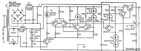
Silicon diodes in full-wave bridge feed seven-transistor regulator. Temperature-compensated silicon-junction zenet diode is basic reference element. Output is constant within 50 my, for use with digital-analog converter.-N. Aron, Precise Converter takes Current Analog of Digital voltage Pulses, Electronics, 35:32, p 68-71. (View)
View full Circuit Diagram | Comments | Reading(654)
80_watt_switching_regulator_supply_for_CATV_applications_with_24_volt_3_ampere_output
Published:2009/7/20 21:47:00 Author:Jessie
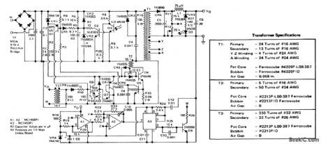
80-watt switching regulator supply for CATV applications with 24-volt 3-ampere output. This circuit operates above 18 kilohertz from a 40- to 60-volt 60-hertz square wave or from a DC standby source with input/output isolation (courtesy Motorola Semiconductor Products Inc.). (View)
View full Circuit Diagram | Comments | Reading(1041)
PENTODE_WITH_CONSTANT_REFERENCE_CURRENT
Published:2009/7/20 21:45:00 Author:Jessie
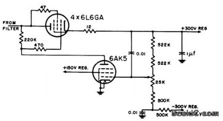
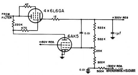
screen is fed directly from regulated voltage of shunt-regulating supply using VR-105 and VR-150 reference lubes to give -300 v.-NBS, Handbook Preferred Circuits Navy Aeronautical Electronic Equipment, Vol. 1, Electron Tube Circuits, 1963, p N2-2. (View)
View full Circuit Diagram | Comments | Reading(715)
Line_operated_inverter_with_15_volt_DC_225_watt_output_
Published:2009/7/20 21:44:00 Author:Jessie
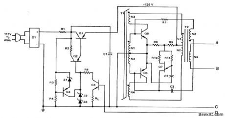
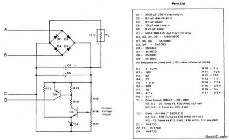
Line-operated inverter with 15-volt DC 225-watt output (courtesy Motorola Semiconductor Products Inc.). (View)
View full Circuit Diagram | Comments | Reading(776)
TWIN_TRIODE_CASCADE_1
Published:2009/7/20 21:43:00 Author:Jessie
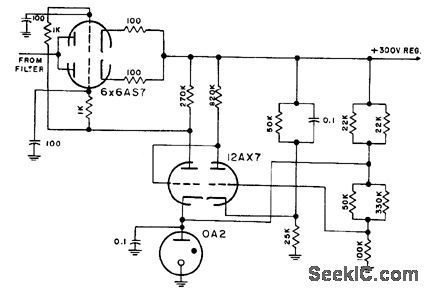
Smaller load resistor improves frequency response. Both reference tube and comparison divider are loaded.-NBS, Handbook Preferred Circuits Navy Aeronautical Electronic Equipment, Vol. 1, Electron Tube Circuits, 1963, p N2-3. (View)
View full Circuit Diagram | Comments | Reading(798)
CURRENT_LIMITING_SUPPLY_WITH_REFERENCE_AMPLIFIER
Published:2009/7/20 21:41:00 Author:Jessie
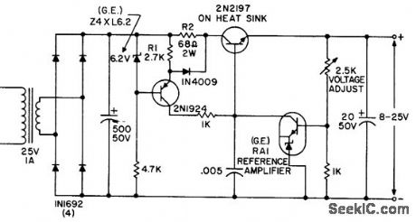
Variable 8 to 25-v supply limits output to 100 mc for protection against short-circuits. Regulation is 0.02% for line voltages from 105 to 130 v.- Transistor Manual, Seventh Edition, General Electric Co., 1964, p 232. (View)
View full Circuit Diagram | Comments | Reading(689)
DUAL_POLARITY_VARIABLE_D_C_SUPPLY
Published:2009/7/21 5:55:00 Author:Jessie
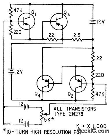
Diagonally symmetrical power transistor circuit permits smooth load current variation over range of several amperes at either polarity. Rectifier supply can be used in place of storage batteries. Maximum current drain from two 12-V dry cells in 5K potentiometer control circuit is 7 ma.-R. R.Bockemuehl, Transistor Rectifier Gives D-C of Either Polarity, Electronics, 32:25, p 76. (View)
View full Circuit Diagram | Comments | Reading(590)
| Pages:129/291 At 20121122123124125126127128129130131132133134135136137138139140Under 20 |
Circuit Categories
power supply circuit
Amplifier Circuit
Basic Circuit
LED and Light Circuit
Sensor Circuit
Signal Processing
Electrical Equipment Circuit
Control Circuit
Remote Control Circuit
A/D-D/A Converter Circuit
Audio Circuit
Measuring and Test Circuit
Communication Circuit
Computer-Related Circuit
555 Circuit
Automotive Circuit
Repairing Circuit