
Index 424
STR-6656 switching power supply thick-film integrated circuit diagram
Published:2011/5/6 4:39:00 Author:Ecco | Keyword: switching power supply , thick-film , integrated circuit
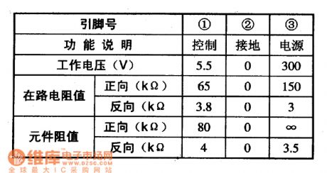
STR-6656 is the switching power supply thick film integrated circuit produced by Sanyo, it is widely used in large screen color (such as Changhong HP Series Rear Projection Color TV) and DVD players, air conditioners, and other switching power supply circuits. 1. Features of functionSTR-6656 integrated circuit includes starting circuit(STAJRT), oscillation circuit (OSC), latch circuit (LATCH), switching tube and driving motivation circuit, overvoltage protection circuit (OVP), overcurrent protection circuit (OCP), over-temperature protection circuit (TSD) and some other ancillary functions circuit. 2. Pin functions STR-6656 IC uses the package with pins in a single line, the pin functions and data are listed in Table. STR-6656 integrated circuit pin functions and data
(View)
View full Circuit Diagram | Comments | Reading(1679)
The typical application circuit of AD7714 programmable sensor signal processor
Published:2011/5/6 4:00:00 Author:Ecco | Keyword: typical application circuit , programmable, sensor , signal processor
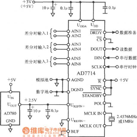
The typical application circuit of AD7714 is shown as the chart. The UDD, UDDA side of AD7714 can be accessed +5 V or +3 V power supply. Analog input is configured for three differential pair inputs. AD780 provides precision +2.5 V reference voltage. When CS non-termination is connected to the DGND, AD7714 is configured into 3-wire serial interface. The quartz crystal (or ceramic resonator) provides the master clock. In some special applications, it requires UDD, UDDA side being controlled by two independent powers.
The typical application circuit of AD7714 5-channel low-power programmable programmable sensor signal processor (View)
View full Circuit Diagram | Comments | Reading(720)
T0P212YA1 PWM monolithic integrated circuit diagram
Published:2011/5/9 1:42:00 Author:Ecco | Keyword: PWM , monolithic, integrated circuit
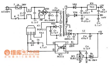

T0P212YA1 is the PWM monolithic switching power supply integrated circuit which is manufactured by the Power Company in the United States, it is widely used in switching power supply circuit of DVD, VCD, etc. DVD players, computers and monitors, air conditioner control system and various other household appliances. 1. pin functions and data T0P212YA1 IC uses separate three-pin package, the pin functions and data are listed in Table. T0P212YA1 integrated circuit pin functions and data 2. The typical application circuit and internal block circuitT0P212YA1 integrated circuit includes an oscillation circuit, driver circuit, various protection circuit. The block diagram of the circuit and the typical application circuit are shown as the chart.
(View)
View full Circuit Diagram | Comments | Reading(669)
TEC9410 4-bit timer / subtraction counter integrated circuit diagram
Published:2011/5/6 3:45:00 Author:Ecco | Keyword: 4-bit, timer , subtraction counter , integrated circuit

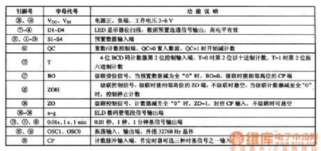
TEC9410 is a 4-bit Timer / subtraction counter IC, which is widely used in time relay, timer and BCD code subtraction counter. TEC9410 IC uses 28-pin dual in-line package, the pin-letter code and pin functions are listed in Table 1. The typical application circuit is shown in Figure 1. Table 1 shows TEC9410 IC pins and pin letter designations. Figure 1 shows the typical application circuit of TEC9410 integrated circuit.
(View)
View full Circuit Diagram | Comments | Reading(1346)
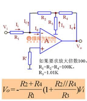
T feedback network circuit diagram
Published:2011/5/9 4:27:00 Author:Ecco | Keyword: T , feedback network
View full Circuit Diagram | Comments | Reading(748)
RY926 ceiling fan speed governing integrated circuit diagram
Published:2011/5/9 3:31:00 Author:Ecco | Keyword: ceiling fan, speed governing, integrated circuit
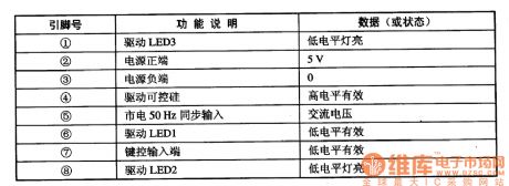

RY926 is the ceiling fan speed governing integrated circuit, which is widely used in the program control circuit of the ceiling fan and power adjusting and automatic light adjustment control of a variety of small household appliances. 1. Pin functions and data RY926 IC uses 8-pin dual in-line package, the pin functions and data are listed in Table. 2. The typical application circuit The ceiling fan speed control system typical application circuit composed of RY926 IC is shown as the chart.
(View)
View full Circuit Diagram | Comments | Reading(2484)
PT2398 reverberation processing integrated circuit diagram
Published:2011/5/9 3:07:00 Author:Ecco | Keyword: reverberation processing , integrated circuit

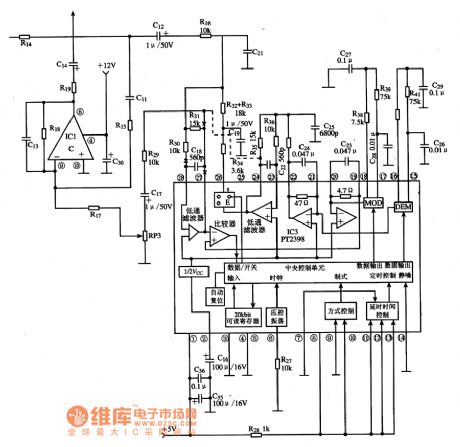
PT2398 is the reverberation processing integrated circuit produced by PT company, it is widely used in various audio systems as reverberation processing. 1. Features of functionsPT2398 IC includes low-pass filter circuit, voltage controlled oscillator circuit, delay time control circuit, mode control circuit, the central control unit circuit and its related subsidiary circuit. 2. Pin functions and data PT2398 IC uses 28-pin dual in-line package, the pin functions and data are listed in Table. 3. The typical application circuit The block diagram and the typical application circuit of PT2398 integrated circuit are shown as the chart.
(View)
View full Circuit Diagram | Comments | Reading(1984)
Four-terminal controllable voltage regulation integrated circuit diagram
Published:2011/5/9 2:37:00 Author:Ecco | Keyword: Four-terminal , controllable , voltage regulation , integrated circuit
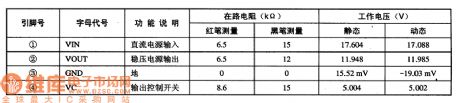
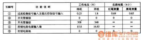
PQ12RD11 is the 12V four-terminal controllable voltage regulator integrated circuit, which is widely used in the controlled power supply circuit of DVD players, color TVs, computer monitors, printers, fax machines and all kinds of household powers. 1. Features of functionsPQ12RD11 IC includes 12V power supply circuit, power supply circuit being ON / OFF control circuit and other ancillary functions circuit. 2. Pin functions and data PQ12RD11 IC is packaged with 4 pins in a single row , the pin functions and data are listed in Table. 3. The typical application circuit The typical application circuit of PQ12RD11 IC is shown in Figure.
(View)
View full Circuit Diagram | Comments | Reading(478)
PQ05MD21 5V four-terminal voltage regulator integrated circuit diagram
Published:2011/5/9 3:16:00 Author:Ecco | Keyword: 5V, four-terminal , voltage regulator , integrated circuit
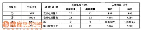
PQ05MD21 is the 5V controlled voltage regulator four-terminal integrated circuit, which is widely used as voltage regulator circuit in DVD players, color TV, computer monitors, and a variety of household electrical power supply.1. Features of functionsPQ05MD21 IC includes 5V power supply circuit, power supply circuit on / off control circuit, and other ancillary functions circuit. 2. Pin functions and data PQ05MD21 IC is packaged with 4 feet in a single row, the pin functions and data are listed in Table. 3. The typical application circuit The power typical application circuit composed of PQ05MD21 integrated circuit is shown as Figure.
(View)
View full Circuit Diagram | Comments | Reading(545)
10-point common anode logarithmic display driver circuit diagram composed of TA7612AP
Published:2011/5/9 2:49:00 Author:Ecco | Keyword: 10-point , common anode , logarithmic , display, driver
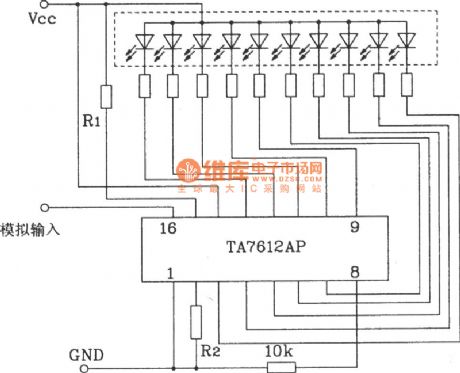
10-point common anode logarithmic display driver circuit diagram composed of TA7612AP is shown as the chart.
The input signalof thiscircuit is an analog voltage input with a logarithmic scale display.
(View)
View full Circuit Diagram | Comments | Reading(1380)
Static driver interface diagram
Published:2011/5/9 3:00:00 Author:Ecco | Keyword: Static driver , interface
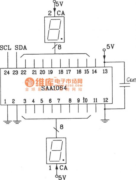
The static driver interface circuit diagram between SAA1064 serial I2C bus and LED display driver integrated circuit
In the quiescent mode, LED uses directly two 8-bit output port driver and it does not need to add an external driver. As the static drivers do not need to switch the scan circuit, the directly external capacitor side CEXT in the figure is connected to ground directly or Vcc. The ends of Vcc and VEE are added to decoupling capacitor, the general value is 0.01μF.
(View)
View full Circuit Diagram | Comments | Reading(583)
8-bit static LED display circuit diagram
Published:2011/5/9 2:46:00 Author:Ecco | Keyword: 8-bit, static, LED display
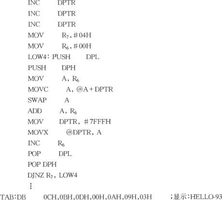
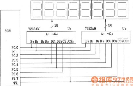
The 8-bit static LED display circuit composed of ICM7212AM 4-bit parallel display / decoder / driver (hardware decoding) The following is the programming process list of 8-character HELL0-98 . The 8 characters are stored in the beginning of the byte unit of table TAB in this program, R7 stores count data, R6 stores data temporarily.
(View)
View full Circuit Diagram | Comments | Reading(2003)
TC89101P memory integrated circuit diagram
Published:2011/5/9 2:13:00 Author:Ecco | Keyword: memory, integrated circuit
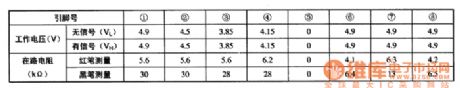
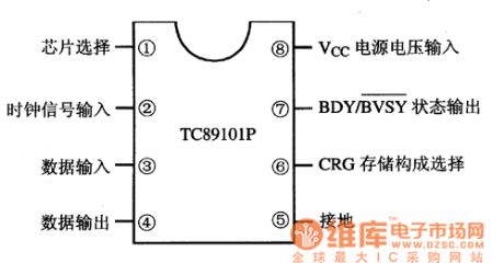
TC89101P is the memory integrated circuit produced by Toshiba, it is widely used in color television sets, air conditioning, audio and other system control circuit. 1. Features of functionsTC891O1P integrated circuit is mainly composed of memory matrix circuit, the selection circuit composed of CRG storage, the register circuit, data input / output interface circuit. 2. Pin functions and data TC89101P IC uses the package with 8 feet in the column, the pin functions are shown in Figure 1, the operating parameters are listed in Table 1.
(View)
View full Circuit Diagram | Comments | Reading(1190)
TOP223Y PWM monolithic integrated circuit diagram
Published:2011/5/9 1:34:00 Author:Ecco | Keyword: PWM , monolithic, integrated circuit


TOP223Y is th PWM monolithic switching power supply integrated circuit which is manufactured by the Power Company in the United States, it is widely used in switching power supply circuit of DVD, VCD, etc. DVD players, computers and monitors, air conditioner control system and various other household appliances. 1. pin functions and data TOP223Y IC uses separate three-pin package, the pin functions and data are listed in Table. T0P223Y integrated circuit pin functions and data 2. The typical application circuit The block diagram of TOP223Y integrated circuit and typical application circuit are shown as the chart. The block diagram and typical application circuit of TOP223Y IC
(View)
View full Circuit Diagram | Comments | Reading(2683)
high performance release in pairs circuit
Published:2011/5/7 13:16:00 Author:John | Keyword: high performance release in pairs circuit

The firgue shows the high performance release in pairs circuit. It is applicable for particularly strict release in pairs circuit. And it also can be used in general release in a receiver. Advantages for these circuits are high gain, excellent load capacity, good reliability and simple circuit. It also has a wide range for AGG. When used in pairs, consistency of amplitude frequency and phase frequency can be helpful to achieve very high targets. (View)
View full Circuit Diagram | Comments | Reading(590)
TTL state probe circuit
Published:2011/5/8 21:21:00 Author:Nicole | Keyword: TTL state probe
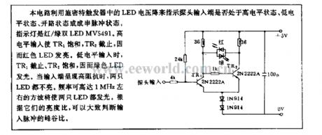
This circuit uses LED voltage drop of Schmitt trigger to indicate whether the probe input terminal is in high level state, low level state, open circuit state or string pulse state. The indicator light is red/green double LED MV5491. When it is high level input, TR1 is saturation, TR2 turns off, so red LED lights. When it is low level input, TR1 turns off, TR2 is saturation, so green LED lights. When the input terminal is high impedance, the two LEDs are all off. The square wave with 1MHz maximum frequency can make two LEDs light. According to their brightness ratio, it can judge the peak-to-trough ratio of input pulse. (View)
View full Circuit Diagram | Comments | Reading(359)
LC2lB-DDC storage integrated circuit diagram
Published:2011/5/6 3:06:00 Author:Nicole | Keyword: storage
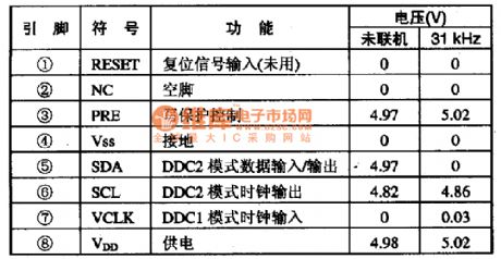
LC2lB is a DDC memory integrated circuit, it is widely used in all kinds of computer displays, such as PHILIPS, Lenovo and so on.
1, functions and features
LC2lB integrated circuit contains I square bus interface circuit, DDC pattern data singal process circuit, memory store unit circuit, writing protection control circuit and some other assistant functions circuits.
2, pin function and data
LC2lB integrated circuit adopt 8-foot dual in-line package, the pin function and data of this integrated circuit is shown in the table1.
(View)
View full Circuit Diagram | Comments | Reading(515)
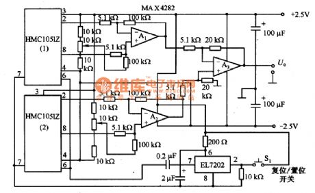
The application circuit diagram of magnetic resistance integrated circuit HMC1051Z
Published:2011/5/9 2:59:00 Author:Nicole | Keyword: magnetic resistance, integrated circuit
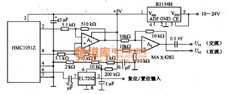
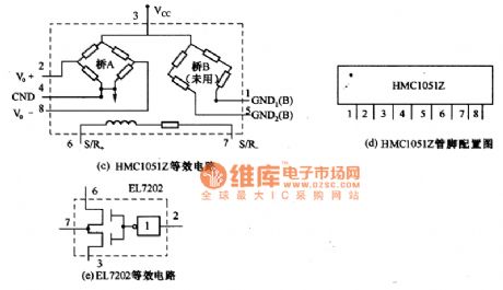
The figure1 is the application circuit of magnetic resistance integrated circuit HMC1051Z. The circuit in the figure1(a) adopts +5V single power supply, A1 also is amplifier circuit, the total amplification is 100 times. U01 outputs AC singal, U02 outputs DC singal, the output singal indicates the strength of magnetic field which is measured by HMC10512.
The circuit in the figure1(b) adopts two 1HMClO51Z to eliminate the influence of stray magnetic field, it adopts ± 2.5 V power supply, U01 output is the strength of related magnetic field.
(a)magnetic field measuring circuit diagram
(b)magnetic field measuring circuit diagram
The figure1 is the application circuit diagram of magnetic resistance integrated circuit HMC1051Z (View)
View full Circuit Diagram | Comments | Reading(863)
Digital linear circuit diagram
Published:2011/5/6 1:41:00 Author:Nicole | Keyword: digital, linear
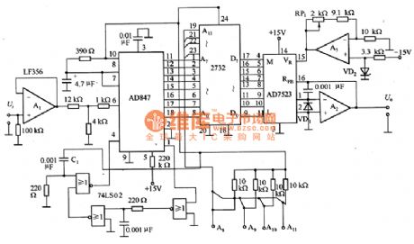
The figure1 is a digital linear circuit. The characteristic of sensor is nonlinear, in order to improve the measurement accuracy on applications, they should be linearized. The linear circuit has all kinds of ways, but the adjusting is trouble. This circuit adopts digital, it can store the linear data in EPROM, it has high stability.
Mimic imput signal Ui is unipolar 0~+lOV singal. A1 is buffer, it is used in transform impedance, then it can match with the low input impedance of A/D converter AD847. When it is connected to power supply, the rising edge of power supply voltage is divided by C1, then it will produce trigger pulse singal. The output data of AD847 is OOH一FFH, it is connected to the address Ao一A7 of 2732.
(View)
View full Circuit Diagram | Comments | Reading(756)
LMX2336LTMX-frequency synthesizer integrated circuit diagram
Published:2011/5/9 1:33:00 Author:Nicole | Keyword: frequency synthesizer
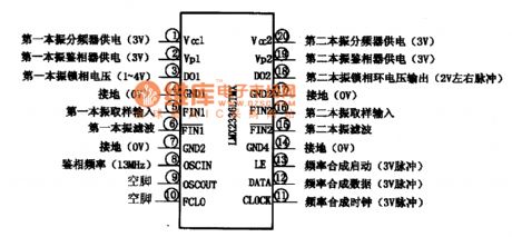
LMX2336LTMX is a frequency synthesizer integrated circuit which is produced by National Semiconductor Corporation, it is widely used in Samsung GSM telephone circuit, such as SGH6O0C、SGH800.
1. functions and features
LMX2336LTMX integrated circuit contains the first, second local oscillator frequency divider circuit, phase-locked loop frequency synthesis start-up circuit, phase-locked loop frequency synthesis data circuit, phase-locked loop frequency synthesis color circuit and other assistant functions circuits.
2. pin function and data
LMX2336LTMX integrated circuit adopts 20-foot dual in-line package, the pin arrangement and pin function and data is shown in the figure1. This IC and LMX2336LTMX can be used interchangeably.
(View)
View full Circuit Diagram | Comments | Reading(556)
| Pages:424/471 At 20421422423424425426427428429430431432433434435436437438439440Under 20 |
Circuit Categories
power supply circuit
Amplifier Circuit
Basic Circuit
LED and Light Circuit
Sensor Circuit
Signal Processing
Electrical Equipment Circuit
Control Circuit
Remote Control Circuit
A/D-D/A Converter Circuit
Audio Circuit
Measuring and Test Circuit
Communication Circuit
Computer-Related Circuit
555 Circuit
Automotive Circuit
Repairing Circuit