
Index 432
Dual LED alternate flasher circuit diagram
Published:2011/5/3 1:13:00 Author:Ecco | Keyword: Dual, LED, alternate , flasher
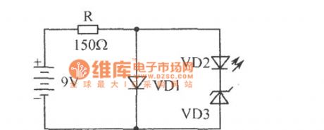
The chart shows the dual LED alternate flasher circuit diagram. It is an interesting two alternately flashing circuit only composed of four elements. VD1 is a flashing light-emitting diode, VD2 is the ordinary light emitting diode. The working course is as follow: VD1 needs 5V, 30mA. When it gets power, VD1 light turns on when there is about 5V voltage being applied to the VD2 and VD3 in series, VD3 is 6.2V regulator diode, so VD3 does not work, then only the VD1 stops, the supply voltage is added to the VD2, VD3 by being limited by R, and then VD3 regulator works, the current flowing through the VD2 and it emits light, VD1 flashing, VD1, VD2 shine alternately.
(View)
View full Circuit Diagram | Comments | Reading(999)
5V/10A 20kHz blocking ammeter transformator using SIPMOS transistor
Published:2011/4/19 21:48:00 Author:May | Keyword: 5V/10A 20kHz, blocking ammeter transformator, SIPMOS transistor
This circuit is convertor which can change input DC voltage (+20~+30V) to lower DC output voltage (+5V). Integrated circuit TDB0555B is time base circuit which can generate 20kHz square wave. The timing time of output (pin 3) is between 10~40μs. Fixed bias can make T1 to break over. Square wave voltage outputted by TDB0555B is differential to triangle wave voltage by R4, C5 and R6+R7. It also can make T1 to cut off. So T1's output is square wave. Then the transformer can output AC and DC voltage after rectifying and filtering before passing opposite phase grade, drive grade and power amplifier grade.Main technical data: input voltage: +20~30V (rated value is 24V);output voltage: +5V;output current: 10A;network voltage adjustment rate: ±0.5%;load voltage adjustment rate: ±2%;efficiency: 78% (when the input voltage is 24V) (View)
View full Circuit Diagram | Comments | Reading(485)
Bridge type voltage regulator circuit using voltage regulator tube
Published:2011/4/19 22:17:00 Author:May | Keyword: Bridge type, voltage regulator, voltage regulator tube

The circuits in diagram (a)~(c) can have very high voltage-regulation coefficient. If voltage regulator tube's internal resistance rz is constant, it has infinity voltage-regulation coefficient when the bridge is keeping precise balance.
The circuit load in diagram (a) is connecting on the bridge diagonal line. When the middle point on the voltage regulation range is satisfying the condition of R1/rz=R2/R3, the resistance of this circuit is about rz+R3. In order to drop down the voltage loss of R3, output voltage must be equal to voltage regulator tube's working voltage.
The circuit in diagram (b) is particularly suitable for stable low voltage. Output voltage is approximately equal to the difference of two voltage regulator tube's working voltage, Uz1-Uz2. Output resistor is rz1-rz2+R3.
The circuit in diagram (c) is only suitable for the situation when the difference value between input voltage and output voltage is very small. The working voltage of two voltage regulators tube is better to be equal. Two resistors R2 and R3 should be the same too. Selection of R2, R3 is middle of working area. (View)
View full Circuit Diagram | Comments | Reading(805)
Single flashing light-emitting diode application circuit
Published:2011/5/3 1:04:00 Author:Ecco | Keyword: Single, flashing , light-emitting diode , application circuit
The chart shows the single flashing LED application circuit. The working frequency of blinking light-emitting diodes is only a few hertz, it is easy to arouse people's attention, it can be widely used in all kinds of alarm circuits, such as temperature, liquid level, the more limited voltage alarm circuit.
(View)
View full Circuit Diagram | Comments | Reading(755)
Fuse fusing indicator circuit diagram
Published:2011/5/3 0:56:00 Author:Ecco | Keyword: Fuse fusing indicator
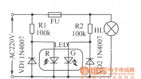
The chart shows the fuse fusing indicator circuit diagram. LED-R is used for the AC power indicator, LED-G is a fuse FU status indicator. When FU is normal, the two LEDs are lit and emit orange light; when FU blows, LED-G is off, only the LED-R emits red light. Limiting resistor R10, R2 can be replaced by the 220nF/450V capacitor, VD1, VD2 can be saved.
(View)
View full Circuit Diagram | Comments | Reading(992)
The typical application circuit of LC227 IC
Published:2011/5/2 20:58:00 Author:Ecco | Keyword: typical application circuit, IC

The typical application circuit
The hood control system typical application circuit composed of LC227A integrated circuit is shown as the chart.
The typical application circuit of LC227 IC is shown as the chart.
(View)
View full Circuit Diagram | Comments | Reading(399)
Series Inductance Circuit
Published:2011/4/30 19:43:00 Author:Robert | Keyword: Series Inductance

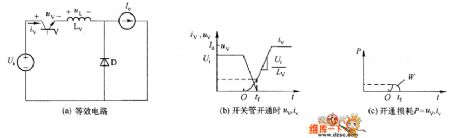
The most simplest open absorbing circuit is thatthe inductance Lv connects to the switchingtubein series, which shows in picture (a). Picture(b) and (c) separately shows the uv, iv and P curve of the opening process. This illustrates thatafter adding series inductance, it limits the switching tube current's uprising speed , and decrease the power dissipation of the switch.
(View)
View full Circuit Diagram | Comments | Reading(442)
Ratio Detection Circuit
Published:2011/5/1 21:48:00 Author:Felicity | Keyword: Ratio Detection Circuit

View full Circuit Diagram | Comments | Reading(742)
Basic Circuit Diagram of SSB Phase-shift
Published:2011/5/1 22:32:00 Author:Felicity | Keyword: Basic Circuit Diagram of SSB Phase-shift,
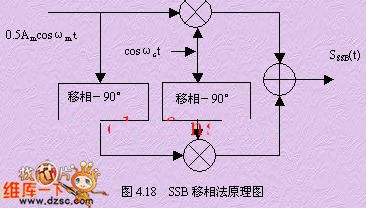
View full Circuit Diagram | Comments | Reading(593)
Telephone signals sending circuit diagram
Published:2011/4/29 4:45:00 Author:Rebekka | Keyword: Telephone signals sending
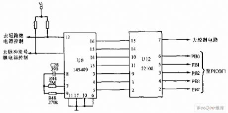
Telephone signals sending circuit is shown as below. U8 is signals sending integrated circuit. The model is 145409. U12 (22100) is a 4X4 cross-matrix circuit (CD22100 is also known as four-way switch). The control circuit is used as U8. (View)
View full Circuit Diagram | Comments | Reading(1340)
Single-end forward converter circuit with RC and diode clamping circuit
Published:2011/4/21 21:37:00 Author:May | Keyword: Single-end, forward converter, RC and diode clamping
Single-ended forward converter has with removing magnetic winding and diode clamping circuit. Above which we talked about is the one with removing magnetic winding. The diagram shows single-end forward converter circuit with RC and diode clamping circuit. After VTl is cut off, winding N1 and VD3, R, C constitute a single-ended fly-back converter, the magnetizing current IM is attenuated by VD3, the reverse polarity voltage of N1 is superimposed on the input voltage U1 and applied between the emitters of VTl, that is Uce1 = Ui + Uc. Obviously, when U1 is greater than Uc, the cut-off time, toff will be less than on-time ton, that is the biggest turn-on pulse width can exceed half of the period. The conduction pulse width allows more, which can get a larger power output. The downside is that VTl will bear higher voltage, excitation energy will be consumed in resistor R. (View)
View full Circuit Diagram | Comments | Reading(496)
Analog rocket emitting electronic game circuit diagram
Published:2011/4/29 4:04:00 Author:Ecco | Keyword: Analog , rocket emitting, electronic game

View full Circuit Diagram | Comments | Reading(1039)
Advanced video game circuit diagram
Published:2011/4/29 4:02:00 Author:Ecco | Keyword: Advanced , video game
View full Circuit Diagram | Comments | Reading(1260)
AC Welder no-load automatic stop circuit diagram
Published:2011/4/29 3:57:00 Author:Rebekka | Keyword: AC Welder, no-load automatic stop

AC Welder no-load automatic stop circuit diagram is shown as above. (View)
View full Circuit Diagram | Comments | Reading(1333)
LED electronic clock circuit diagram with six functions
Published:2011/4/29 3:43:00 Author:Ecco | Keyword: LED , electronic clock , six functions

The LED electronic clock circuit with six functions shown as the chart is composed of XY01 modules. It has six functions of showing month, day, hours, minutes, seconds and alarm.
(View)
View full Circuit Diagram | Comments | Reading(493)
A simple inverter circuit diagram made by TL494
Published:2011/4/29 3:34:00 Author:Ecco | Keyword: simple inverter

A simple inverter circuit made by TL494 is shown as the chart.
(View)
View full Circuit Diagram | Comments | Reading(4487)
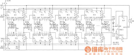
DSM-872 Typical Application Circuit (b) circuit diagram
Published:2011/4/29 1:30:00 Author:Ecco | Keyword: Typical Application Circuit
In the circuit shown as the chart, the high and low level of pin 3,pin 4 changes alternately, SCR1 and SCR2 will turn alternately, then the lamps will flash alternately.
(View)
View full Circuit Diagram | Comments | Reading(386)
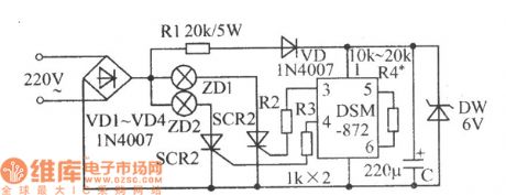
DSM-872 Typical application circuit (1) circuit diagram
Published:2011/4/29 1:40:00 Author:Ecco | Keyword: Typical application circuit

In the circuit shown as the chart, the high and low level of pin 3,pin 4 changes alternately, the LED1 and LED2 will flash alternately.
(View)
View full Circuit Diagram | Comments | Reading(451)
IR2156 fluorescent lamp integrated circuit electron ballast
Published:2011/4/23 3:36:00 Author:May | Keyword: fluorescent lamp, integrated, electron ballast

IR2156 can offer solution of high cost-effectiveness for fluorescent electron ballast. It can integrate lighting tube error protection and the programmable working frequency with warm-up, lighting and ballast continue working.
(View)
View full Circuit Diagram | Comments | Reading(2439)
Start-up circuit adopts FET
Published:2011/4/14 5:57:00 Author:may | Keyword: Start-up, FET

View full Circuit Diagram | Comments | Reading(526)
| Pages:432/471 At 20421422423424425426427428429430431432433434435436437438439440Under 20 |
Circuit Categories
power supply circuit
Amplifier Circuit
Basic Circuit
LED and Light Circuit
Sensor Circuit
Signal Processing
Electrical Equipment Circuit
Control Circuit
Remote Control Circuit
A/D-D/A Converter Circuit
Audio Circuit
Measuring and Test Circuit
Communication Circuit
Computer-Related Circuit
555 Circuit
Automotive Circuit
Repairing Circuit