Basic Circuit
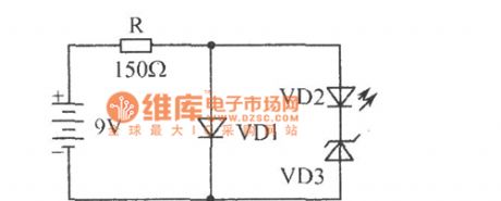
Dual LED alternate flasher circuit diagram
Published:2011/5/3 1:13:00 Author:Ecco | Keyword: Dual, LED, alternate , flasher | From:SeekIC

The chart shows the dual LED alternate flasher circuit diagram. It is an interesting two alternately flashing circuit only composed of four elements. VD1 is a flashing light-emitting diode, VD2 is the ordinary light emitting diode. The working course is as follow: VD1 needs 5V, 30mA. When it gets power, VD1 light turns on when there is about 5V voltage being applied to the VD2 and VD3 in series, VD3 is 6.2V regulator diode, so VD3 does not work, then only the VD1 stops, the supply voltage is added to the VD2, VD3 by being limited by R, and then VD3 regulator works, the current flowing through the VD2 and it emits light, VD1 flashing, VD1, VD2 shine alternately.
Reprinted Url Of This Article:
http://www.seekic.com/circuit_diagram/Basic_Circuit/Dual_LED_alternate_flasher_circuit_diagram.html
Print this Page | Comments | Reading(3)

Article Categories
power supply circuit
Amplifier Circuit
Basic Circuit
LED and Light Circuit
Sensor Circuit
Signal Processing
Electrical Equipment Circuit
Control Circuit
Remote Control Circuit
A/D-D/A Converter Circuit
Audio Circuit
Measuring and Test Circuit
Communication Circuit
Computer-Related Circuit
555 Circuit
Automotive Circuit
Repairing Circuit
Code: