Index 6
Pyroelectric detection and radio transmitter circuir diagram
Published:2011/9/26 2:15:00 Author:Rebekka | Keyword: Pyroelectric detection , radio transmitter
View full Circuit Diagram | Comments | Reading(693)
Electric single-girder crane radio remote control(TX315B1) circuit diagram
Published:2011/10/19 20:47:00 Author:Rebekka | Keyword: Electric single-girder crane , radio remote control

Four operation functions of the circuit: Mobile electric hoist travel hook (hanging objects) can do up and down movements. The right half part of the dotted line in the figureis the operation of cranes in the original circuit. K1 ~ K4 are the original manual operation buttons. Now they are used to replace the relay contacts, SQ is the improving limiting switch. KM1 ~ KM4 are the AC relays that are used to control the motor to enhance the motor M1 and M2. It controls and rises the forewardandreversal rotation of hanging objects. The dotted lines ofleft halfpart inthe figure form the new radio remote control circuit. In the circuit, the four output ends A ~ D of TX315B1 receiving circuit canrespectively drive tubes VT ~ VT4. (View)
View full Circuit Diagram | Comments | Reading(3829)
Multi-channel infrared remote control lighting
Published:2011/10/18 2:52:00 Author:Rebekka | Keyword: Multi-channel infrared, remote control lighting
View full Circuit Diagram | Comments | Reading(1751)
Chang an Alto Car engine ignition system circuit diagram
Published:2011/10/20 2:32:00 Author:Rebekka | Keyword: Chang an Alto Car , engine ignition system
View full Circuit Diagram | Comments | Reading(1425)
Chang an antelope car air-conditioning system circuit diagram
Published:2011/10/20 2:31:00 Author:Rebekka | Keyword: Chang an antelope , air-conditioning system

1. Heater motor 2. Electrical load signal isolation diode 3. High and low pressure protection switch 4.A / C switch 5. Evaporator thermistor 6. Engine coolant temperature sensor 7. Condenser fan control relay 8. Condenser the fan motor 9. Compressor and clutch assembly 10. Main relay 11. Controller Ground 12. Heater switch 13. Compressor relay 14. Power Ground A connects to fuse (20A) (IC2), B connects to A / C fuse (15A), C connects to F; fuse (20A), D connects to IG1 fuse (15A)
(View)
View full Circuit Diagram | Comments | Reading(1510)
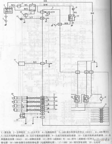
chang an Antelope car ABS circuit diagram
Published:2011/9/15 22:53:00 Author:Rebekka | Keyword: chang an Antelope , car ABS

chang'an Antelope car ABS circuit diagram is shown as above.
1. Battery 2. The total fuse 3. Ignition switch 4. 5.ABS fuse circuit hydraulic unit electronic control unit (ECU) 6.ABS warning light 7. The right hand wheel speed sensor 8. Left rear wheel speed sensor 9. The right front wheel speed sensor 10. left front wheel speed sensor 12. diagnostic connector 13. stop (or brake) light 14. stop (or brake) light switch 16.ABS failsafe relay (solenoid valve relay) 17.ABS 18. hydraulic pump motor 19. solenoid valve (View)
View full Circuit Diagram | Comments | Reading(949)
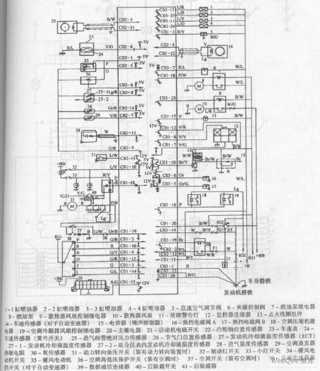
Chang an antelope car engine circuit diagram
Published:2011/10/18 2:55:00 Author:Rebekka | Keyword: Chang an antelope, Car Engine

Chang antelope car engine circuit diagram is shown above. (View)
View full Circuit Diagram | Comments | Reading(827)
Fifth way wireless burglar alarm system (FDD5/JDD5) circuit diagram
Published:2011/10/20 1:50:00 Author:Rebekka | Keyword: Fifth way, wireless burglar alarm system

The picture(a) shows the code transmission circuit. FDD5 has set the digital coding circuit. It can be pre-encoded by encoder circuit, in use. As long as the connected components get power, it will automatically launch the emission signal. The picture(b) shows the remote control receiver decoding circuitry. JDD5 also integrated within the decoding circuit VD5027. (View)
View full Circuit Diagram | Comments | Reading(1118)
Numerical coding wireless remote control dimming circuit diagram
Published:2011/10/20 1:55:00 Author:Rebekka | Keyword: Numerical coding , wireless remote control dimming

This circuit uses the wireless remote control component TWH630/TWH631 and encoding four dimming circuits TH9801/TH9802. It is composed of the wireless transmitter and receiver decoding controller. Pressing the transmitter button, you can control the brightness of incandescent lamps in accordance with the weak, medium, high, off. (A) is the transmitter circuit; (b) is the receiver circuit. (View)
View full Circuit Diagram | Comments | Reading(2530)
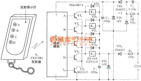
Four way remote control AC switching circuit diagram
Published:2011/9/28 4:33:00 Author:Rebekka | Keyword: Four way remote control, AC switching

As shown, the circuit consists of TX315B1 type transmitter / receiver components to receive decoder circuit of four high output control signal. Driving through the transistor connected to four self-locking relay to AC power. Receive Groups pieces of the output of the A ~ D access VT1 ~ VT4 four relay driver tubes, each drive tube drives a self-locking relay output Io K. VT5 is formed by the emitter of VT1 ~ VT4 channel controller. Only when Io output signal decoding effective after the VT5 conduction, VT1 ~ VT4 are possible to conduct. (View)
View full Circuit Diagram | Comments | Reading(2682)
The doppler effect automatic switching circuit using RD9481
Published:2011/10/19 22:48:00 Author:Rebekka | Keyword: Doppler effect, automatic switching

RD9481 is a special hybrid microwave integrated circuit object displacement detection. It can accurately detect moving objects. Its internal circuitryis composed ofthe microwave transceiver circuits. It is composed of two gated amplifiers, voltage comparator, state controller, the delay timer, blocked the timer and reference voltage source. (View)
View full Circuit Diagram | Comments | Reading(1414)
Beijing grand cherokee car charging system circuit diagram
Published:2011/10/20 2:12:00 Author:Rebekka | Keyword: Beijing grand cherokee, car charging system
View full Circuit Diagram | Comments | Reading(860)
Wireless remote electric car circuit diagram
Published:2011/10/18 1:57:00 Author:Rebekka | Keyword: Wireless remote electric car

The electric model car remote controller can make model car go forward, astern and also turn right or left. The structure is simple and easy to operate. The radio remote control receiver demodulation circuit uses TWH9238 components. The supporting remote control transmitter components TWH9236 is shown in the figure. (View)
View full Circuit Diagram | Comments | Reading(5614)
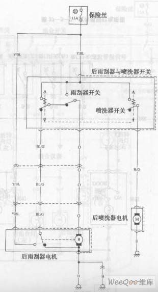
Chang an Star multifunction rear wiper and jetter circuit diagram
Published:2011/10/20 22:18:00 Author:Rebekka | Keyword: Chang an Star , multifunction , rear wiper , jetter
View full Circuit Diagram | Comments | Reading(629)
Chang an Star multi-purpose vehicle cooling system circuit diagram
Published:2011/10/20 2:34:00 Author:Rebekka | Keyword: Chang an Star, multi-purpose vehicle , cooling system

1. Battery 2. Fuse 3. Ignition switch 4. Fuse box 5. Main fuse 6. Condenser fan motor, compressor fuse 7. Air conditioning fuse 8. Air conditioning relay 9. Fan motor 10. Fan motor resistor 11. Air conditioning and fans the motor switch 12. diode 13. heater fan motor 14. heater fan resistor 15. heater fan switch 16. high and low pressure protection switch 17. evaporator temperature sensor 18. condenser fan motor relay 19. condenser fan motor 20. compressor relay 21. air conditioning compressor 22. Air conditioning amplifier 23.ECM (View)
View full Circuit Diagram | Comments | Reading(693)
Chang an Star multifunction vehicle ABS circuit diagram
Published:2011/10/20 2:34:00 Author:Rebekka | Keyword: Chang an Star, multifunction vehicle ABS

B-black B/BL-black/blue BW-black/white BL-blue BL/B-blue/black BL/W-blue/white G-green G/B-green/black G/W-green/white Lg-light green Lg/B-light green/balck P/B-Pink/black R-red R/BL-red/blue R/W-red/white V-purple W-white W/BL-white/blue W/G-white/green Y-yellow Y/B-yellow/black Y/W-yellow/black Y/W-yellow/black Y/W-yellow/white
1. Battery 2. Fuse 3. Ignition switch 4. 5.ABS electronic control circuit fuse unit 6.ABS warning lights 7.ABS solenoid valve relay 8.ABS pump motor relay 9. Diode 10.ABS hydraulic unit 10-1. Pump motor 10-2. Solenoid valve 11.Right rear wheel speed sensor 12. Left rear wheel speed sensor 13. The right front wheel speed sensor 14. The left front wheel speed sensor 15. Diagnostic Block 16. Stop lamps 17. Stop light switch (View)
View full Circuit Diagram | Comments | Reading(575)
Chang an Star SUV 6350C engine control system circuit diagram
Published:2011/10/20 2:34:00 Author:Rebekka | Keyword: Chang an Star SUV, engine control system

1. Air conditioning condenser temperature sensor 2. Coolant Temperature Sensor 3. Inlet air pressure and temperature sensors 4. Throttle position sensor 5. Hall sensor 6. Knock sensor 7. Oxygen sensor 8. Speed sensor 9. Air conditioning switch 10. Heater switch 11. Idle stepper motor 12-1. Gang injector 13-2. Gang injector 14-3. Gang injector 15-4. Gang injector 16. solenoid valve 17. Electric Fuel Pump 18. Fuel pump relay 19. Air conditioning relay 20. main relay 21. High-voltage ignition coil 23. Fault diagnosis socket 24. Accumulator
(View)
View full Circuit Diagram | Comments | Reading(1249)
Chang an Star SUV 6350B engine control system circuit diagram
Published:2011/10/20 2:33:00 Author:Rebekka | Keyword: Chang an Star SUV, engine control system

Changan Star SUV 6350B engine control system circuit diagram is shown as above.
1. Camshaft position sensor 2. Crankshaft position sensor 3. Intake manifold pressure sensor 4. Throttle position sensor 5. Engine coolant temperature sensor 6. Intake air temperature sensor 7.8. Empty 9. Oxygen sensor 10. Speed sensor 11 . heater switch 12.Air conditioning control module 13.Light switch 14.In light switch 16.Data transmission connector 17.ABS electronic control unit 18. Tachometer 20.2 19.No1 fuel injector 20. No 2 fuel injectors fuel injectors 22.4 21.No.3 No. 24-valve fuel injectors 23.EGR. Canister magnetic valve 24-1. Fuel pressure regulator vacuum switch valve 25. idle air control valve 26. radiator fan relay 27. radiator fan motor 28. diagnostic interface 29. pump relay 30. fuel pump 31. fault indicator 32. ignition coil assembly 33. ignition ring assembly 34. ignition switch 35. main relay 36. starter solenoid switch 37. accumulator 38. Engine Electronic Control Unit (View)
View full Circuit Diagram | Comments | Reading(924)
Instrument wiring(with electroniccompass) circuit 2 of Mitsubishi Pajero light off-road vehicle
Published:2011/10/20 22:00:00 Author:Rebekka | Keyword: Mitsubishi Pajero , light off-road vehicle , automobile instrument wiring, electroniccompass

Wiring Color
B: Black LG: light green G: Green L: Blue W: White Y: Yellow SB: sky blue BR; Brown 0: Orange GR: Gray R: red P: Pink V: Purple
(View)
View full Circuit Diagram | Comments | Reading(930)
The structure of photodiode
Published:2011/9/26 22:16:00 Author:Rebekka | Keyword: photodiode, structure
View full Circuit Diagram | Comments | Reading(575)
| Pages:6/164 1234567891011121314151617181920Under 20 |
Circuit Categories
power supply circuit
Amplifier Circuit
Basic Circuit
LED and Light Circuit
Sensor Circuit
Signal Processing
Electrical Equipment Circuit
Control Circuit
Remote Control Circuit
A/D-D/A Converter Circuit
Audio Circuit
Measuring and Test Circuit
Communication Circuit
Computer-Related Circuit
555 Circuit
Automotive Circuit
Repairing Circuit


