Index 21
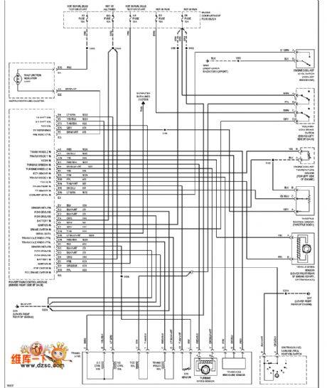
Cadillac transmission gear circuit diagram
Published:2011/8/25 1:06:00 Author:Ecco | Keyword: Cadillac transmission gear
View full Circuit Diagram | Comments | Reading(646)
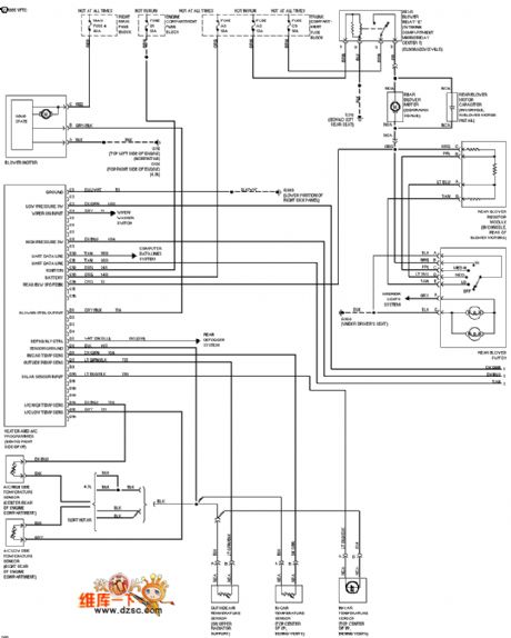
Cadillac air-conditioning circuit diagram
Published:2011/8/25 1:06:00 Author:Ecco | Keyword: Cadillac air-conditioning
View full Circuit Diagram | Comments | Reading(899)
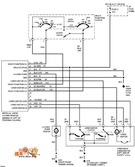
Cadillac reversing light circuit diagram
Published:2011/8/25 1:05:00 Author:Ecco | Keyword: Cadillac , reversing light
View full Circuit Diagram | Comments | Reading(674)
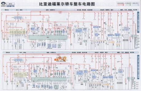
BYD Flyer vehicle circuit diagram
Published:2011/8/25 1:19:00 Author:Ecco | Keyword: BYD Flyer vehicle
View full Circuit Diagram | Comments | Reading(3538)
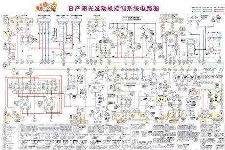
Nissan sunny engine control system circuit diagram
Published:2011/8/25 1:52:00 Author:Ecco | Keyword: Nissan , sunny engine , control system
View full Circuit Diagram | Comments | Reading(2241)
function and data of pins of integrated circuit TDA94295
Published:2011/7/24 3:10:00 Author:chopper | Keyword: function, data, pins, integrated circuit
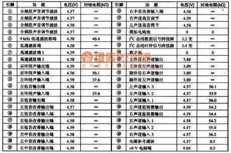
TDA9429S is the new audio signal switching and processing integrated circuit produced by Philips,which is widely used in TV acoustics,home theater and other audio devices.1.Function characteristicsTDA9429S IC includes sub-band adjustable sound control circuit, surround sound signal processing circuit, audio signals of left and right channel of the main and sub processing circuit. High,middle,low signals improvement circuit, the left, right channel monitor circuit, and other auxiliary circuits
(View)
View full Circuit Diagram | Comments | Reading(766)
pins and data of integrated circuit TDA9380,TDA9383
Published:2011/7/24 3:02:00 Author:chopper | Keyword: pins, data, integrated circuit
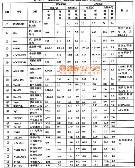
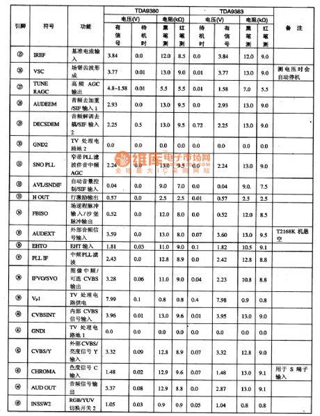
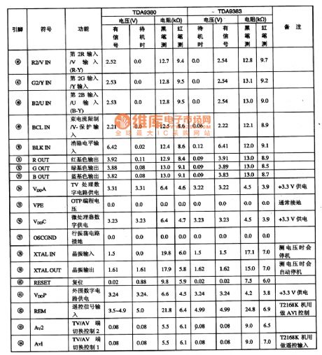
TDA9380,TDA9383——Microcomputer, IF, video, field line scanning small signal processing monolithic IC. TDA9380, TDA9383 is the newest ultra large scale monolithic specific integrated circuit produced by Philips,which is used in the latest generation of TV, such as Kangjia K/N series TVs.1.Function characteristics TDA9380, TDA9383 integrated circuit includes microcomputer control circuit, the IF signal processing circuit, video signal processing circuit, field line scanning small signal processing circuit. It is an large-scale integrated circuit which can integrate the TV small signals as a unit except a high-frequency tuner.
(View)
View full Circuit Diagram | Comments | Reading(3410)
function and data of pins of integrated circuit TDA9860
Published:2011/7/26 5:54:00 Author:chopper | Keyword: function, data, pins, integrated circuit
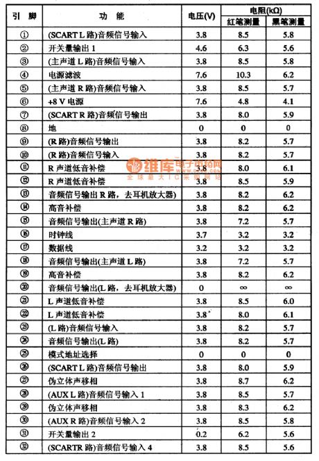
TDA9860 —— I(2)C Bus control universal Hi-Fi audio signal processing integrated circuit. TDA9860 is a Hi-Fi audio signal processing integrated circuit produced by Philips,which is widely used in large-screen TV and RPTV, home theater and computer, DVD player and other audio systems.1.function characteristics TDA9860 IC can switch the input of three-way stereo audio signal or six-way single channel audio signal to the one of the SC / L light,speaker and earphone for outputting.
(View)
View full Circuit Diagram | Comments | Reading(1128)
function and data of pins of integrated circuit
Published:2011/7/26 5:46:00 Author:chopper | Keyword: function, data, pins, integrated circuit
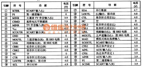
TDA9859 —— I(2)C Bus control sound source switching, audio processing integrated circuit TDA9859 is the sound source switching,audio processing integrated circuit produced by Philips,which is widely used in domestic and imported large-screen color TVs.1.function characteristics
TDA9859 integrated circuit contains the accompanying signal of main channel switching and processing circuit, I(2)C bus interface circuit, high and low turning point setting circuit, R and L channel audio signal processing circuit, reference voltage circuit, pseudo-stereo setting circuit, the analog site selecting and input signal processing circuit, and other auxiliary circuits. (View)
View full Circuit Diagram | Comments | Reading(1435)
function and data of pins of integrated circuit TDA9815
Published:2011/7/25 2:37:00 Author:chopper | Keyword: function, data, pins, integrated circuit
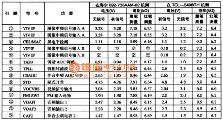
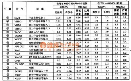
TDA9815--Intermediate frequency signal processing integrated circuit TDA9815 is the intermediate frequency signal processing integrated circuit produced by Philips,which is applied to large-screen color TVs.1.function characteristics TDA9815 IC contains the image intermediate frequency signal processing circuit, accompanying sound IF signal processing circuit, voltage-controlled oscillator circuit, the image IF input switch circuit, standard switching circuit, medium-level AGC circuit,tuner AGC circuit, AFT control circuit, and other auxiliary circuits.
(View)
View full Circuit Diagram | Comments | Reading(653)
function and data of pins of TDA9808T integrated circuit
Published:2011/7/25 2:30:00 Author:chopper | Keyword: function, data, pin, integrated circuit
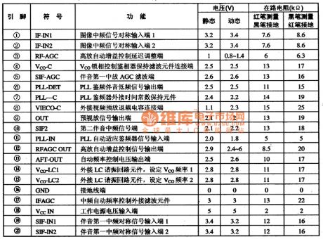
TDA9808T--quasi sound separation, PLL frequency discrimination and intermediate frequency processing integrated circuit. TDA9808T is the PLL frequency discriminator IF processing integrated circuit of quasi-audio-visual separation produced by Philips,which is widely used in various screen color TVs, its function and data of pins are listed in Table 78.
(View)
View full Circuit Diagram | Comments | Reading(702)
Numeral Display Memory Doorbell Circuit
Published:2011/8/12 7:03:00 Author:Sue | Keyword: Numeral Display, Memory Doorbell

Numeral display memory doorbell circuit. (View)
View full Circuit Diagram | Comments | Reading(882)
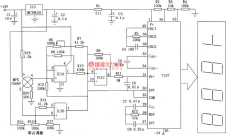
Digital Electronic Scale Composed of A/D Converter 7107
Published:2011/8/14 6:56:00 Author:Sue | Keyword: Digital, Electronic Scale, Converter
View full Circuit Diagram | Comments | Reading(4295)
Frequency Shift Modulator Composed of CA3020,MC723
Published:2011/8/18 7:58:00 Author: | Keyword: Frequency Shift, Modulator

The circuit's main component uses digital integrated circuit which can be used in frequency range of 1-10kHz. Its identification precision is high so that it can detect small frequency shift as small as 1%. The picture shows the frequency shift modulator circuit. IC1 is wide frequency amplifier CA3020. It constitutes the circuit's input terminal whose differential output are put on IC2(JK trigger MC723)'s J,K input terminals. GATE circuit IC3 constitutes monostable multivibrator, and its timing cycle is equal to half period of central frequency. Its input signal will gate the trigger after it is time delayed by the monostable multivibrator. (View)
View full Circuit Diagram | Comments | Reading(648)
Multi-channel Display Circuit Composed of CD4017
Published:2011/8/18 6:53:00 Author: | Keyword: Multi-channel, Display
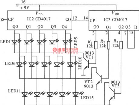
As seen in the pciture, when two CD4017's output terminals are connected in a certain combination and are added some corresponding control circuits, there will be a multi-channel output states display circuit. The circuit consists of two CD4017, three transistors and fifteen LEDs, and it is 15 circuits output display circuit. In the circuit, IC2 uses 5 output terminals of Q0-Q4. IC3 uses 3 output terminals of Q0-Q2. IC2's 5 output terminals are divided into 3 groups which are connected 15 LEDs in parallel. Every group of 5 LEDs are controlled by IC3's 3 output terminals through VT1-VT3 and are displayed in 3 groups. (View)
View full Circuit Diagram | Comments | Reading(5171)
Oscillating Circuit Composed of CD4518
Published:2011/8/11 8:13:00 Author:Sue | Keyword: Oscillating Circuit
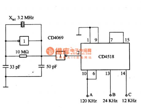
The picture shows oscillating circuit which composed of CD4518. The circuit is composed of BCD counter CD4518 and crystal oscillator(3.2MHZ). A,B,C terminals will output signals of frequency of 120KHZ, 241KHZ,12kHZ respectively. The working voltage is 10V. (View)
View full Circuit Diagram | Comments | Reading(2360)
Multi-channel Voltage Cyclic Detection Circuit(NE555,CD4066)
Published:2011/8/18 6:37:00 Author: | Keyword: Multi-channel Voltage, Cyclic Detection
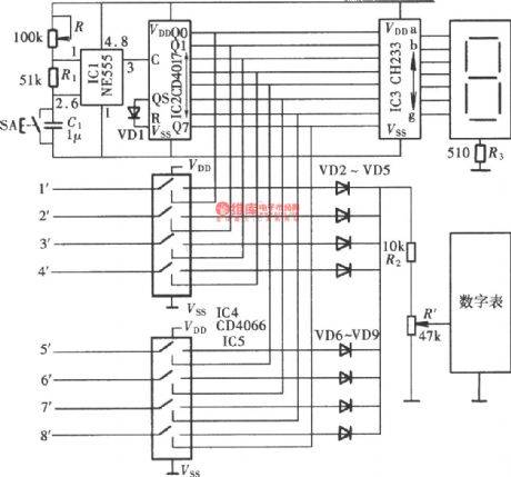
The multi-channel voltage cyclic detection circuit is used to realise integrated control of the production facility. The device can detect every production device's working voltage automatically in a given time interval so that the watchstander can know the working state of the device according to the detection result and handle the problem in time when any irregularity occurs. The picture shows the circuit which consists of cyclic detection pulse generator, cyclic detection pulse distributor, cyclic detection channel optional switch and channel display. The largest cyclic detection channel is eight-channel. (View)
View full Circuit Diagram | Comments | Reading(1652)
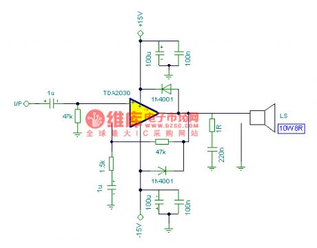
8W Amplifier Circuit
Published:2011/8/11 5:53:00 Author:Sue | Keyword: Amplifier
View full Circuit Diagram | Comments | Reading(563)
Channel 6 Input Mixer Circuit
Published:2011/8/14 6:45:00 Author:Sue | Keyword: Channel 6, Input Mixer
View full Circuit Diagram | Comments | Reading(720)
The Mazda 95PROBE charging system circuit
Published:2011/8/14 8:42:00 Author:Christina | Keyword: Mazda, charging system circuit
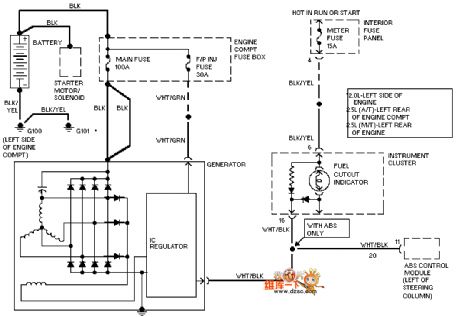
The Mazda 95PROBE charging system circuit is as shown in the figure:
(View)
View full Circuit Diagram | Comments | Reading(1878)
| Pages:21/164 At 202122232425262728293031323334353637383940Under 20 |
Circuit Categories
power supply circuit
Amplifier Circuit
Basic Circuit
LED and Light Circuit
Sensor Circuit
Signal Processing
Electrical Equipment Circuit
Control Circuit
Remote Control Circuit
A/D-D/A Converter Circuit
Audio Circuit
Measuring and Test Circuit
Communication Circuit
Computer-Related Circuit
555 Circuit
Automotive Circuit
Repairing Circuit
