Index 32
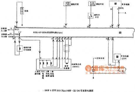
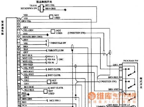
BMW8 Series of EGS 35pin (4HP-22/24) transmission circuit diagram 1
Published:2011/8/3 2:20:00 Author:Ecco | Keyword: BMW8 Series , EGS , 35pin transmission
View full Circuit Diagram | Comments | Reading(489)
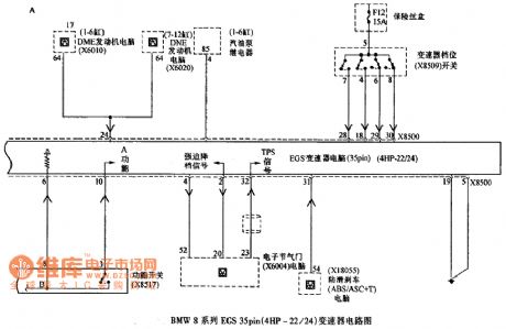
BMW8 Series of EGS 35pin (4HP-22/24) transmission circuit diagram 2
Published:2011/8/3 2:22:00 Author:Ecco | Keyword: BMW8 Series , EGS 35pin transmission
View full Circuit Diagram | Comments | Reading(489)
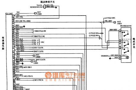
BMW5 Series of 35-pin transmission circuit diagram
Published:2011/8/3 1:54:00 Author:Ecco | Keyword: BMW5 Series , 35-pin transmission
View full Circuit Diagram | Comments | Reading(478)
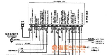
BMW6 Series of 35-pin transmission circuit diagram
Published:2011/8/3 1:55:00 Author:Ecco | Keyword: BMW6 Series , 35-pin transmission
View full Circuit Diagram | Comments | Reading(428)
BMW7 Series of 35-pin transmission circuit diagram
Published:2011/8/3 1:56:00 Author:Ecco | Keyword: BMW7 Series , 35-pin transmission
View full Circuit Diagram | Comments | Reading(468)
The ABS system circuit diagram for BMW cars
Published:2011/8/3 2:26:00 Author:Ecco | Keyword: ABS system, BMW cars
View full Circuit Diagram | Comments | Reading(549)
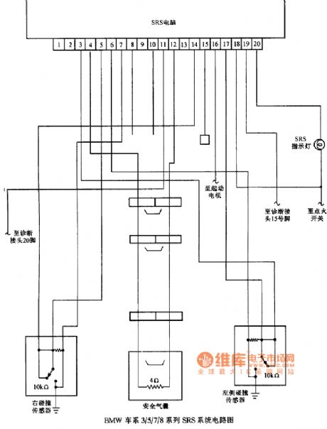
BMW 3/5/7/8 series of SRS system circuit diagram
Published:2011/8/3 1:16:00 Author:Ecco | Keyword: BMW , 3/5/7/8 series , SRS system
View full Circuit Diagram | Comments | Reading(497)
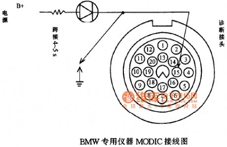
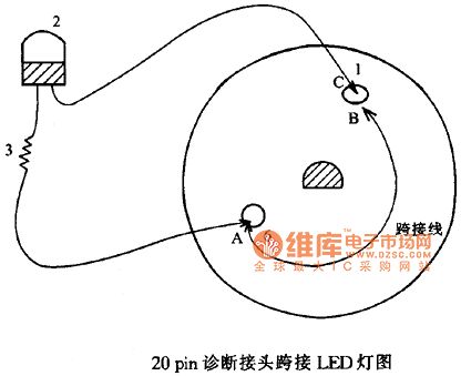
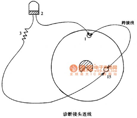
BMW SRS light flash reading fault code circuit diagram on the instrument
Published:2011/8/3 1:15:00 Author:Ecco | Keyword: BMW , SRS light flash , reading fault code , instrument
View full Circuit Diagram | Comments | Reading(463)
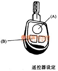
The button A circuit diagram on BMW pressing key
Published:2011/8/2 22:21:00 Author:Ecco | Keyword: button A , BMW pressing key
View full Circuit Diagram | Comments | Reading(515)
BMW 6 Series of 55-pin computer SRS system circuit diagram
Published:2011/8/2 22:50:00 Author:Ecco | Keyword: BMW , 6 Series , 55-pin computer , SRS system
View full Circuit Diagram | Comments | Reading(492)
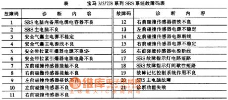
BMW 3/5/7/8 series of SRS system fault code table circuit diagram
Published:2011/8/2 22:47:00 Author:Ecco | Keyword: BMW , 3/5/7/8 series , SRS system , fault code table
View full Circuit Diagram | Comments | Reading(577)
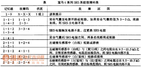
BMW 6 Series of SRS system fault code table circuit diagram
Published:2011/8/2 22:30:00 Author:Ecco | Keyword: BMW 6 Series , SRS system, fault code table
View full Circuit Diagram | Comments | Reading(496)
BMW 3/5/7/8 series of SRS system circuit diagram 1
Published:2011/8/2 22:37:00 Author:Ecco | Keyword: BMW , 3 series, 5 series, 7 series, 8 series, SRS system
View full Circuit Diagram | Comments | Reading(567)
BMW 3/5/7/8 series of SRS system circuit diagram 2
Published:2011/8/2 22:38:00 Author:Ecco | Keyword: BMW , 3 series, 5 series, 7 series, 8 series, SRS system
View full Circuit Diagram | Comments | Reading(464)
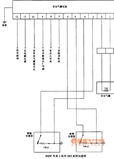
BMW 6 series of SRS system circuit diagram
Published:2011/8/2 22:38:00 Author:Ecco | Keyword: BMW , 6 series , SRS system
View full Circuit Diagram | Comments | Reading(567)
Horn and Danger Signal Principle Diagram of Beijing CHEROKEE BJ2021 Light Off-road Vehicle
Published:2011/7/23 2:09:00 Author:Michel | Keyword: CHEROKEE, Light Off-road Vehicle, Horn, Danger Signal, Principle Diagram

Picture:Horn,Water Washing,Air Conditioning, Steering and Danger Signal Principle diagram of Beijing CHEROKEE BJ2021 Light Off-road Vehicle
l-buzzer,12-key switch,34-horn relay,35-horn button,36-electronic horn,44-compression hunger electromagnetic clutch,45-voltage switch,46-temperature switch,47-pour lamp,48-pour lamp switch,49-turn signal flasher unit,50-alarm flasher,51-steering and danger alertion switch,52-right steering signal light and steering indicator,53-left steering signal light and steering indicator 55-brake switch (View)
View full Circuit Diagram | Comments | Reading(733)
__AUTODRUM
Published:2009/7/6 7:06:00 Author:May
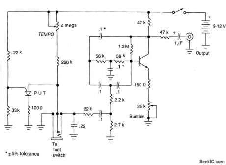
This unit generates a drum-like damped oscillation that sounds best when fed into a higher power amplifier. The beat rate may be determined by operating a foot pedal in much the same manner as for a real drum, or by means of an internal oscillator, the speed of which may be preset.
(View)
View full Circuit Diagram | Comments | Reading(688)
ST24C04 I2C bus data storage IC diagram
Published:2011/5/9 21:40:00 Author:Rebekka | Keyword: bus data storage IC
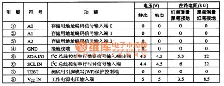
ST24C04 and I2C are bus data memory integrated circuits. It is widely used for video, audio, air conditioning and other appliances remote control system. It is compatible with single-chip microcomputer to finish the storage and recall functions of program.The pre-stored program of ST24C04 IC changes with different application occasions. So pay attention to the chage of memorizer.ST7C04 integrated circuit uses 8-pin dual in-line package, the pin functions and data of the integrated circuit are listed in Table 1.
(View)
View full Circuit Diagram | Comments | Reading(495)
Mitsubishi Pajero light off-road vehicle assistant socket wiring circuit diagram
Published:2011/5/10 1:06:00 Author:Rebekka | Keyword: Mitsubishi Pajero, assistant socket

Mitsubishi Pajero light off-road vehicle assistant socket wiring circuit diagram is shown as above.
Wiring Color
B: Black LG: light green G: Green L: Blue W: White Y: Yellow SB: sky blue BR: Brown 0: Orange GR: Gray R: red P: Pink V: Purple (View)
View full Circuit Diagram | Comments | Reading(838)
Mitsubishi Pajero light off-road vehicle central control door lock set (continued) wiring circuit diagram
Published:2011/5/10 1:07:00 Author:Rebekka | Keyword: Central control door lock set , Mitsubishi Pajero, light off-road vehicle

Mitsubishi Pajero light off-road vehicle central control door lock set (continued) wiring circuit diagram is shown as above.
Wiring Color B: Black LG: light green G: Green L: Blue W: White Y: Yellow SB: sky blue BR: Brown 0: Orange GR: Gray R: red P:Pink V: Purple (View)
View full Circuit Diagram | Comments | Reading(1751)
| Pages:32/164 At 202122232425262728293031323334353637383940Under 20 |
Circuit Categories
power supply circuit
Amplifier Circuit
Basic Circuit
LED and Light Circuit
Sensor Circuit
Signal Processing
Electrical Equipment Circuit
Control Circuit
Remote Control Circuit
A/D-D/A Converter Circuit
Audio Circuit
Measuring and Test Circuit
Communication Circuit
Computer-Related Circuit
555 Circuit
Automotive Circuit
Repairing Circuit
