Automotive Circuit
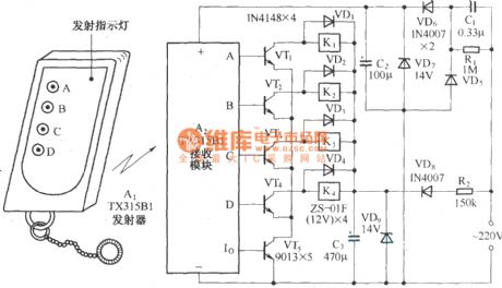
Four way remote control AC switching circuit diagram
Published:2011/9/28 4:33:00 Author:Rebekka | Keyword: Four way remote control, AC switching | From:SeekIC

As shown, the circuit consists of TX315B1 type transmitter / receiver components to receive decoder circuit of four high output control signal. Driving through the transistor connected to four self-locking relay to AC power. Receive Groups pieces of the output of the A ~ D access VT1 ~ VT4 four relay driver tubes, each drive tube drives a self-locking relay output Io K. VT5 is formed by the emitter of VT1 ~ VT4 channel controller. Only when Io output signal decoding effective after the VT5 conduction, VT1 ~ VT4 are possible to conduct.
Reprinted Url Of This Article:
http://www.seekic.com/circuit_diagram/Automotive_Circuit/Four_way_remote_control_AC_switching_circuit_diagram.html
Print this Page | Comments | Reading(3)

Article Categories
power supply circuit
Amplifier Circuit
Basic Circuit
LED and Light Circuit
Sensor Circuit
Signal Processing
Electrical Equipment Circuit
Control Circuit
Remote Control Circuit
A/D-D/A Converter Circuit
Audio Circuit
Measuring and Test Circuit
Communication Circuit
Computer-Related Circuit
555 Circuit
Automotive Circuit
Repairing Circuit
Code: