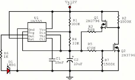
Circuit Diagram
Index 254
Repeating Timer No.2
Published:2012/12/5 0:05:00 Author:muriel | Keyword: Repeating Timer

This circuit is based on a simple asymmetric oscillator. The length of time the relay remains energized - and the length of time it remains de-energized - are set independently. With the component values shown in the diagram - both periods are adjustable from about 1 to 30 minutes. (View)
View full Circuit Diagram | Comments | Reading(791)
Repeating Interval Timer
Published:2012/12/5 0:04:00 Author:muriel | Keyword: Repeating Interval Timer

This circuit has an adjustable output timer that will re-trigger at regular intervals. The output period can be anything from a fraction of a second to half-an-hour or more - and it can be made to recur at regular intervals of anything from seconds to days and beyond. (View)
View full Circuit Diagram | Comments | Reading(792)
24 Second Shot Clock 2
Published:2012/12/5 0:04:00 Author:muriel | Keyword: 24 Second , Shot Clock

This is a circuit intended to be used in basketball shot clock. (View)
View full Circuit Diagram | Comments | Reading(1417)
555 Pulse Generator
Published:2012/12/5 0:03:00 Author:muriel | Keyword: 555 Pulse Generator
View full Circuit Diagram | Comments | Reading(0)
24 Hour Timer
Published:2012/12/5 0:02:00 Author:muriel | Keyword: 24 Hour , Timer
View full Circuit Diagram | Comments | Reading(1004)
Asymmetric Timer
Published:2012/12/5 0:01:00 Author:muriel | Keyword: Asymmetric Timer
View full Circuit Diagram | Comments | Reading(772)
Periodic Timer
Published:2012/12/5 0:01:00 Author:muriel | Keyword: Periodic Timer
View full Circuit Diagram | Comments | Reading(828)
5 to 30 Minute Timer
Published:2012/12/5 0:01:00 Author:muriel | Keyword: 5 to 30 Minute, Timer
View full Circuit Diagram | Comments | Reading(627)
NE555 Monostable
Published:2012/12/5 Author:muriel | Keyword: NE555 Monostable
View full Circuit Diagram | Comments | Reading(899)
Sound Level Meter
Published:2012/12/4 23:56:00 Author:muriel | Keyword: Sound Level Meter

This is a simple, battery operated, sound level meter using a microphone as input for comparison of sound levels. (View)
View full Circuit Diagram | Comments | Reading(0)
Simple Wideband RF Millivoltmeter
Published:2012/12/4 23:55:00 Author:muriel | Keyword: Simple Wideband , RF Millivoltmeter
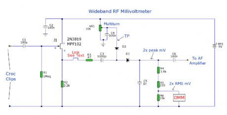
Professional test equipment is expensive to buy or hire. But the opportunity is here as below, to emulate a commercial RF millivoltmeter in cheap and simple terms, by its DC output driving a digital multimeter display.
In lieu of access to a radio communications test set, frequency bandwidth response can only be estimated as being good to a few hundred Mhz and an input level range from 1mV to a couple of volts rms. Perhaps a reader giving feedback to CXI could firm up these estimates with proper lab kit.
So the finished unit will do a satisfactory job for hobby use in fault tracing, gain measurement and general radio test work. Don't forget to halve the indicated DMM reading for the true rms input!
Please note this unit is NOT intended to measure RF power, as its sensitive components would be destroyed by the inputting of high RF voltages. (View)
View full Circuit Diagram | Comments | Reading(4072)
50hz Calibration aid for Multimeters
Published:2012/12/4 23:54:00 Author:muriel | Keyword: 50hz , Calibration aid, Multimeters

The purpose of this prototype unit does away with the need for an oscillator. It offers a mains-derived and fully variable 50 hz AC volts down to millivolts for comparison and to check accuracy, of two or more parallel connected multimeters. (View)
View full Circuit Diagram | Comments | Reading(1056)
PC Scope Probe
Published:2012/12/4 23:53:00 Author:muriel | Keyword: PC Scope Probe
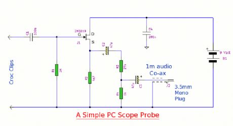
This simple pc scope probe is nothing more than a fet follower. It has a high input impedance and a low output impedance to match a mic or line input socket on a pc or laptop. (View)
View full Circuit Diagram | Comments | Reading(1281)
Small General Purpose Audio Test Set
Published:2012/12/4 23:52:00 Author:muriel | Keyword: Small General Purpose, Audio Test Set

This is a small general purpose audio test set. It comprises a low 0.3% distortion phase shift oscillator and a level meter. The level meter is set at 100mV FSD and can be used for gain measurements and general testing. Current consumption is just under 4mA. (View)
View full Circuit Diagram | Comments | Reading(1484)
RF Probe
Published:2012/12/4 23:52:00 Author:muriel | Keyword: RF Probe
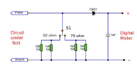
This RF probe can be used at High Frequency (HF) or Ultra High Frequency (UHF) on both 50 and 75 ohm coaxial cables. In addition the RF voltage can be measured under load or no-load conditions which allows the circuit to double as an RF Watt meter. The RF probe can be used for oscillators and small transistors for powers up to 2 Watts. (View)
View full Circuit Diagram | Comments | Reading(0)
Transistor Tester
Published:2012/12/4 23:51:00 Author:muriel | Keyword: Transistor Tester

A test circuit for BJT (Bipolar Junction Transistors). This circuit can measure both small signal hfe and DC current gain hFE of a low to medium power power transistor. In addition it can measure collector-base and collector-emitter leakage current. This circuit can also measure hFE at different operating points. A multimeter can be used at multiple test sockets to make all measurements, or two DC ammeters can be used. (View)
View full Circuit Diagram | Comments | Reading(0)
Field Strength Meter for 2.4 Ghz Wireless LAN
Published:2012/12/4 23:50:00 Author:muriel | Keyword: Field Strength Meter, 2.4 Ghz, Wireless LAN
View full Circuit Diagram | Comments | Reading(2998)
EMF Probe Version 2
Published:2012/12/4 23:49:00 Author:muriel | Keyword: EMF Probe
View full Circuit Diagram | Comments | Reading(1718)
Low Frequency Oscillator
Published:2012/12/4 23:48:00 Author:muriel | Keyword: Low Frequency Oscillator
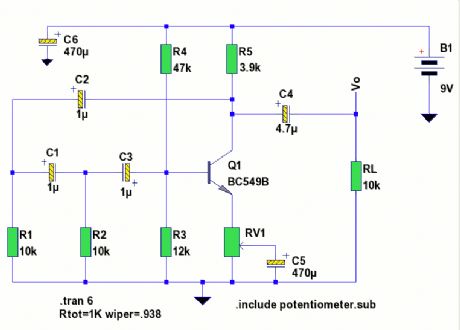
A low frequency test oscillator for testing tone controls and experimenting. (View)
View full Circuit Diagram | Comments | Reading(1679)
Coil Coupled Operation Metal Detector
Published:2012/12/4 23:48:00 Author:muriel | Keyword: Coil Coupled Operation, Metal Detector
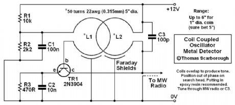
A Coil Coupled Operation Metal Detector made from readily obtainable components and using an ordinary medium receiver as a detector. (View)
View full Circuit Diagram | Comments | Reading(3302)
| Pages:254/2234 At 20241242243244245246247248249250251252253254255256257258259260Under 20 |
Circuit Categories
power supply circuit
Amplifier Circuit
Basic Circuit
LED and Light Circuit
Sensor Circuit
Signal Processing
Electrical Equipment Circuit
Control Circuit
Remote Control Circuit
A/D-D/A Converter Circuit
Audio Circuit
Measuring and Test Circuit
Communication Circuit
Computer-Related Circuit
555 Circuit
Automotive Circuit
Repairing Circuit
