
Circuit Diagram
Index 252
W7ZOI Diplexer
Published:2012/12/6 1:33:00 Author:muriel | Keyword: W7ZOI Diplexer

View full Circuit Diagram | Comments | Reading(1494)
Diode Matching for Mixers
Published:2012/12/6 1:31:00 Author:muriel | Keyword: Diode Matching, Mixers
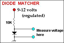
For optimal results Schottky or Hot-Carrier diodes should be used. However, common diodes such as the 1N914, 1N4148 or 1N4454 are all quite suitable and are much cheaper. The four ring diodes should be matched to help mixer balance and thus carrier suppression. At MF and HF the most critical matching required is the forward voltage drop across the diode and this is easily performed with a sensitive voltmeter.
Set your voltmeter on the 2 volt scale to give you 3 decimal places for matching the voltage drops. Try and find 4 diodes close to one another. In addition, best results maybe obtained if all the diodes are the same type (i.e. all 1N4148) and if they are all from the same manufacturer. Look above for easy schematic to match your diodes with a voltmeter. Give the diode under test at least 20 seconds to warm up and stabilize before taking your voltage measurement.
(View)
View full Circuit Diagram | Comments | Reading(2262)
Homebuilding Diode Ring Mixers
Published:2012/12/6 1:31:00 Author:muriel | Keyword: Homebuilding Diode Ring, Mixers

View full Circuit Diagram | Comments | Reading(1989)
Broadband Transformers plus Diode Ring Mixers
Published:2012/12/6 1:30:00 Author:muriel | Keyword: Broadband Transformers, Diode Ring Mixers

There are 2 basic types of broadband transformers used in most QRP work — conventional and transmission line style. Both types may be wound on ferrite toroids, pot cores or rods, however, I only discuss the toroidal transformers we employ to give a 4:1 impedance transformation.
I use these transmission line transformers on many projects on the QRP / SWL HomeBuilder web site. For MF and HF uses, a ferrite core permeability of 850-900 is generally required and the FT37-43 ferrite core proves suitable. Shown above are 3 equivalent schematics of the 4:1 transmission line transformer. You'll probably find that the center drawing easiest to conceptualize, however, with closer examination, all 3 schematics are the same and transform signals from unbalanced 50 Ω impedance up to 200 Ω unbalanced impedance or visa-versa.
The high impedance is 200 Ω and the low impedance is 50 Ω in all cases. It is important to know that these transformers are symmetrical and the points labeled Ground or VCC can be switched with the point labeled High Impedance. (View)
View full Circuit Diagram | Comments | Reading(1450)
Product Detector and Diplexers
Published:2012/12/6 1:28:00 Author:muriel | Keyword: Product Detector, Diplexers
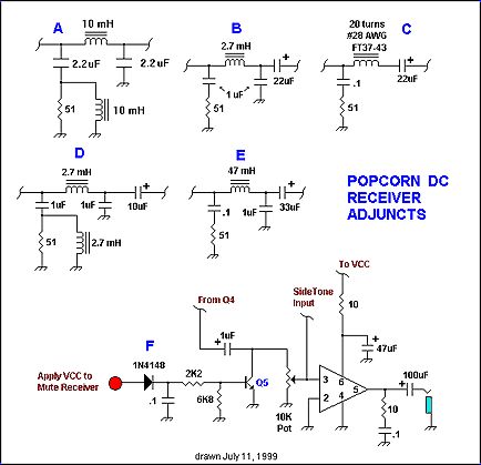
The 50 ohm diode ring product detector can be commercial units such as the Mini-Circuits SBL1 or TUF-1 or homebrewed 50 ohm impedance units. Five simple diplexers are shown in the lower Adjuncts schematic for you to choose from. The one you choose will depend on available parts, cost and your requirements in a popcorn receiver such as this. These diplexers are mostly of the low pass filter variety and provide a ~50 ohm termination to the diode ring mixer and some matching to preserve the product detector dynamic range. I realize that except for (A) and (D) these audio frequency filters are not truly diplexers and will not provide DC to daylight matching. The intent of this web site is not high performance-high cost design and please do not confuse it as such. Note that electrolytic capacitors that bypass to ground such as the 1 uF caps must be non-polarized or bipolar for best results.
The (A) diplexer is by W7ZOI and is described on the Diplexer Web Page on this site.
The (B) and (D) diplexers are my designs and the (D) diplexer is the (B) diplexer with out the high pass component.
The (B) diplexer shown has a 3000 hertz 2 pole high pass/2 pole low pass design. This 2nd order filter provides reasonable overall matching Capacitors are standard-value, non-polar electrolytic types.
The (C) diplexer is a very basic, but very practical choice for this receiver.
The (E) diplexer is one that I used in one of my first DC receivers and the 47 millihenry inductor is a standard value unit sold by Mouser Electronics and others.
Another diplexer choice for this receiver might be the unit described by Rick Campbell, KK7B in his Binaural I-Q receiver project published in the March 1999 issue of QST. (View)
View full Circuit Diagram | Comments | Reading(2426)
Popcorn Direct Conversion Main Frame
Published:2012/12/6 1:28:00 Author:muriel | Keyword: Popcorn Direct Conversion, Main Frame

Shown to the right is the schematic to a low cost popcorn direct conversion receiver main frame. To complete the receiver, a front end band pass filter and a VFO with an output power of 7 dBm is required. This is indeed a frugal project using 4 cheap transistors, an RC low pass filter and an LM386N for output power to a pair of low-impedance headphones. The builder also has a choice of 5 diplexers and an optional mute circuit. This receiver is easily built using Ugly Construction and can be built in 3-4 hours with a bit of luck. (View)
View full Circuit Diagram | Comments | Reading(907)
NPN DC-BIAS
Published:2012/12/6 1:26:00 Author:muriel | Keyword: NPN DC-BIAS
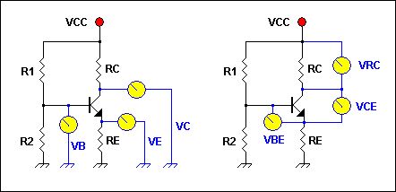
This application calculates the various voltages and currents of a simple voltage divider bias NPN bipolar transistor amp. The following is calculated: IB, IC, IE, VE, VB, VC, VCE and detection of Saturation or Cutoff. The user can alter the VCC, VBE, transistor beta and any of four resistor values R1, R2, RC and RE by picking the transistor value from a standard-value resistor table or manually entering the value. The schematic illustrates some of the voltage measuring points on the transistor schematic. This app is in final BETA. (View)
View full Circuit Diagram | Comments | Reading(957)
Resonator
Published:2012/12/6 1:26:00 Author:muriel | Keyword: Resonator

This application calculates the inductor and capacitor values for the tank circuit of a simple bipolar transistor RF amp. The basic schematic is shown above. Enter the center frequency plus the inductive/capacitive reactance you desire and press the Calculate button to calculate the necessary inductance and capacitance for L and C respectively. (View)
View full Circuit Diagram | Comments | Reading(980)
Universal Diplexer
Published:2012/12/6 1:25:00 Author:muriel | Keyword: Universal Diplexer

Universal Diplexer calculates the inductance and capacitance values for a Bridge-Tee diplexer based upon a chosen superhet receiver intermediate frequency. The diplexer is the Joe Reisert, W1JR popularized design discussed under Diplexer Topics on this web site. The user inputs an IF and presses the Calculate button to have the capacitor and inductor values given in pF and uH respectively. The diplexer schematic is included in the application. Note that the this is for the Q = 1 version of the Bridge-Tee Diplexer. (View)
View full Circuit Diagram | Comments | Reading(1077)
PI Filter Designer
Published:2012/12/6 1:24:00 Author:muriel | Keyword: PI Filter Designer

PI Filter Designer is a simple 3 element 50 ohm input and output impedance pi filter designing application. This program allows the user to design simple lowpass filters by selecting from a variety of standard capacitor values either empirically or to suit what you have on hand. The filter 3 dB cutoff frequency and required L1 inductance are automatically calculated and displayed. In addition, the user may select an additional capacitor value to put in parallel with both caps C1 and C2. In this app XL = XC = 50 ohms impedance. No other impedances can be calculated with this program. (View)
View full Circuit Diagram | Comments | Reading(679)
RF preamp for the 40 Meter band with 3 tuned filters
Published:2012/12/6 1:23:00 Author:muriel | Keyword: RF preamp , 40 Meter band, 3 tuned filters

View full Circuit Diagram | Comments | Reading(1553)
Toroidal Inductor Norton Amp Experiments
Published:2012/12/6 1:23:00 Author:muriel | Keyword: Toroidal Inductor, Norton Amp

View full Circuit Diagram | Comments | Reading(1975)
A Low Noise, High Dynamic Range Broadband RF Amp
Published:2012/12/6 1:22:00 Author:muriel | Keyword: Low Noise, High Dynamic Range, Broadband RF Amp

This schematic is a version of a circuit developed and patented by David Norton and Allen Podell in June 1974. This variation was described by Joe Reisert, W1JR in the now defunct Ham Radio Magazine. The Norton design uses transformer coupling to achieve noiseless negative feedback and is really outstanding. A great article utilizing and augmenting on this technique receivers is by Jacob Makhinson, N6NWP in QST magazine for Feb 1993 with A High Dynamic Range MF/HF Receiver Front End . Makhinson arranged 2 in push-pull to obtain excellent results. Obtain a back-issue of QST for closer study. Note that the fore mentioned Feb QST article has the coil phasing wrong and the correct phasing can be seen at this web site from QST for July 1996. There is also information about Norton feedback RF amplifiers in EMFRD.If you are building a contest-grade receiver and need a good RF preamp and/or post mixer amplifier, the Norton type is quite suitable. An amp built using a 2N5109 can have a noise figure in the 2.5 - 3dB range. I have also built them with 2N3866, MRF517, MRF581 and a 2N5179 although the last transistor would be a somewhat poorer choice. This schematic with a 2N5109 is good from 1.8 to 150 MHz with a 1.2:1 VSWR or less according to Joe Reisert. I have even put one in a friends CB radio and he was delighted. (View)
View full Circuit Diagram | Comments | Reading(3772)
VE7GC Popcorn RF Preamp
Published:2012/12/6 1:21:00 Author:muriel | Keyword: VE7GC , Popcorn, RF Preamp

Here is an easy RF preamp by Dick Pattinson, VE7GC. It uses a single tuned circuit at the front end and can connect directly to a mixer or product detector in a simple receiver project. Note how Dick provided adjustable RF gain control for this circuit in his Wee Willy project on this website. If you can not find Tak Lee green 10.7 MHz IF coils, probably any other brand of 10.7 MHz slug tuned IF transformer would work. The Mouser catalog number is 421F123 . If your 10.7 MHz IF coil has a built in capacitor at the base , remove it. A fixed inductor may also be wound using a powdered iron torroid core and then all or a portion of the C1 capacity would be made variable. The input impedance is 50 ohms and the output impedance is low due to the Q2 emitter follower stage.
(View)
View full Circuit Diagram | Comments | Reading(3823)
RF Preamps
Published:2012/12/6 1:21:00 Author:muriel | Keyword: RF Preamps

Here is a schematic sent to me by W1FB many years ago. It is very similar to a 6M two-stage preamp that he published in QST in the mid eighties. Doug really favored the grounded gate FET for narrow band preamps. His published work is replete with examples of them on just about every band. I built that amp and remember getting about 10 dB gain, which is all that I wanted for the 6M direct conversion receiver using a diode ring detector that I was building. The great feature of the amp is that it combines a band pass filter and preamp in one. I lost the original schematic that Doug sent me but was delighted to see that I made a bitmapped drawing of it on a floppy disk that was recently re-discovered when we were moving an old desk. The shield shown in the schematic was a small piece of grounded ,double sided PC board in which, I made a small chamfered hole in to pass the lead going to the T2 tap. The shield, along with very short component leads will help minimize parasitic oscillations. The T2 tap is 3 turns down from the end of the T2 main winding that connects to the variable capacitor. Doug specified T37-10 cores for the inductors, but I substituted T37-6 cores and used the same number of windings as specified for the T37-10 core inductors. It worked fine. (View)
View full Circuit Diagram | Comments | Reading(1057)
PBUS communication bus
Published:2012/12/6 1:18:00 Author:muriel | Keyword: PBUS communication bus

View full Circuit Diagram | Comments | Reading(1206)
3-wire serial LCD interface
Published:2012/12/6 1:16:00 Author:muriel | Keyword: 3-wire, serial, LCD interface

View full Circuit Diagram | Comments | Reading(1294)
Period timer for aquarium, sprinklers and more
Published:2012/12/6 1:16:00 Author:muriel | Keyword: Period timer, aquarium, sprinklers

View full Circuit Diagram | Comments | Reading(718)
Computer controlled infrared transmitter
Published:2012/12/6 1:15:00 Author:muriel | Keyword: Computer controlled , infrared transmitter

View full Circuit Diagram | Comments | Reading(963)
Dual light timer
Published:2012/12/6 1:14:00 Author:muriel | Keyword: Dual light timer

View full Circuit Diagram | Comments | Reading(717)
| Pages:252/2234 At 20241242243244245246247248249250251252253254255256257258259260Under 20 |
Circuit Categories
power supply circuit
Amplifier Circuit
Basic Circuit
LED and Light Circuit
Sensor Circuit
Signal Processing
Electrical Equipment Circuit
Control Circuit
Remote Control Circuit
A/D-D/A Converter Circuit
Audio Circuit
Measuring and Test Circuit
Communication Circuit
Computer-Related Circuit
555 Circuit
Automotive Circuit
Repairing Circuit