Circuit Diagram
Index 249
Electronic Dice Circuits
Published:2012/12/10 0:53:00 Author:muriel | Keyword: Electronic Dice Circuits
View full Circuit Diagram | Comments | Reading(932)
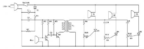
Colour (Sound) Organ
Published:2012/12/10 0:52:00 Author:muriel | Keyword: Colour (Sound) Organ
View full Circuit Diagram | Comments | Reading(834)
Black Light
Published:2012/12/10 0:51:00 Author:muriel | Keyword: Black Light
View full Circuit Diagram | Comments | Reading(1079)
Adjustable Strobe Light
Published:2012/12/10 0:51:00 Author:muriel | Keyword: Adjustable, Strobe Light
View full Circuit Diagram | Comments | Reading(967)
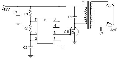
40W Fluorescent Lamp Inverter
Published:2012/12/10 0:50:00 Author:muriel | Keyword: 40W , Fluorescent Lamp, Inverter
View full Circuit Diagram | Comments | Reading(1093)
3 Channel Spectrum Analyzers
Published:2012/12/10 0:49:00 Author:muriel | Keyword: 3 Channel, Spectrum Analyzers
View full Circuit Diagram | Comments | Reading(898)
12VDC Fluorescent Lamp Driver
Published:2012/12/10 0:48:00 Author:muriel | Keyword: 12VDC , Fluorescent Lamp Driver
View full Circuit Diagram | Comments | Reading(725)
Simple Parallel (Printer) Port Interface
Published:2012/12/10 0:47:00 Author:muriel | Keyword: Simple , Parallel (Printer) Port, Interface
View full Circuit Diagram | Comments | Reading(796)
Computer Controlled Frequency Counter/Logic Probe
Published:2012/12/10 0:47:00 Author:muriel | Keyword: Computer Controlled , Frequency Counter/Logic Probe
View full Circuit Diagram | Comments | Reading(798)
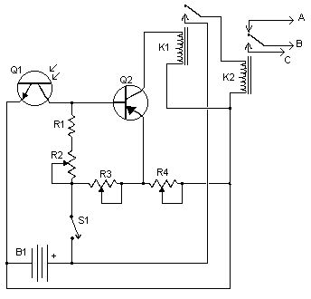
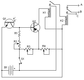
Automatic Headlight Brightness Switchs
Published:2012/12/10 0:46:00 Author:muriel | Keyword: Automatic , Headlight , Brightness Switchs
View full Circuit Diagram | Comments | Reading(595)
Car Alarm Arming Horn Beep Canceller
Published:2012/12/10 0:45:00 Author:muriel | Keyword: Car Alarm Arming, Horn Beep Canceller
View full Circuit Diagram | Comments | Reading(819)
Wireless Auto Tachometer
Published:2012/12/10 0:44:00 Author:muriel | Keyword: Wireless, Auto Tachometer
View full Circuit Diagram | Comments | Reading(1046)
EMF Field Intensity Meter
Published:2012/12/10 0:41:00 Author:muriel | Keyword: EMF, Field Intensity Meter
View full Circuit Diagram | Comments | Reading(1761)
Three Frequency Crystal Marker
Published:2012/12/10 0:40:00 Author:muriel | Keyword: Three , Frequency Crystal Marker
View full Circuit Diagram | Comments | Reading(653)
Phasing Exciter for 75 Meter SSB
Published:2012/12/10 0:40:00 Author:muriel | Keyword: Phasing Exciter, 75 Meter SSB
View full Circuit Diagram | Comments | Reading(1445)
200MHz broadband amplifier circuit diagram with low noise
Published:2012/12/10 0:12:00 Author:Ecco | Keyword: 200MHz, broadband amplifier , low noise
View full Circuit Diagram | Comments | Reading(839)
DC motor servo control circuit diagram
Published:2012/12/10 0:11:00 Author:Ecco | Keyword: DC motor , servo control
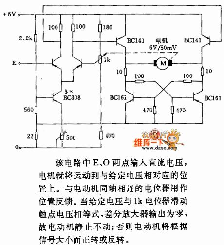
In the circuit, when E, O are input DC voltage, the motor will be moved to a position corresponding with the voltage. The potentiometer connected to the same coaxially of motor is used as position feedback. When the given voltage is equal to 1k potentiometer wiper contact voltage, the differential amplifier output is zero, so the motor is stationary; Otherwise, the motor will be transferred or reversal according to the size of the signal.
(View)
View full Circuit Diagram | Comments | Reading(3387)
Digital Responder timing design circuit
Published:2012/12/10 0:29:00 Author:Ecco | Keyword: Digital Responder , timing

According to the difficulty degree of the grab answer, the host will set the time to answer the question, and the counter is set by preset by preset time circuit, and the counter clock pulse is provided by the second pulse circuit. The preset time circuit is designed by decimal synchronization addition and subtraction counter 74LS192 circuit, and the specific circuit is shown as the figure.
(View)
View full Circuit Diagram | Comments | Reading(1821)
Optical isolation device transmission linearity improving circuit diagram
Published:2012/12/10 0:21:00 Author:Ecco | Keyword: Optical isolation , transmission linearity, improving

It uses negative feedback techniquesto greatly improve the transmission photocoupler linearity.
In figure (a), D1 is in the feedback path, the current flowing D1 has the linear relationship with Vi. The disadvantage of this circuit is not taken into account the non-linear relationship between the current transfer ratio of optocoupler devices and operating current. Therefore, the deviced must be carefully selected.
(View)
View full Circuit Diagram | Comments | Reading(1028)
Microcomputer data acquisition system circuit diagram
Published:2012/12/10 0:15:00 Author:Ecco | Keyword: Microcomputer, data acquisition system

Microcomputer data acquisition system composed of AD570, AD1408 and microprocessor CPU8155 circuit is shown as the figure. The measuring circuit has eight channels, each channel has sequential measurements, the scanning of each channel does not exceed 50μs, the system logic levels use TTL, binary code, data transmission way.
(View)
View full Circuit Diagram | Comments | Reading(1381)
| Pages:249/2234 At 20241242243244245246247248249250251252253254255256257258259260Under 20 |
Circuit Categories
power supply circuit
Amplifier Circuit
Basic Circuit
LED and Light Circuit
Sensor Circuit
Signal Processing
Electrical Equipment Circuit
Control Circuit
Remote Control Circuit
A/D-D/A Converter Circuit
Audio Circuit
Measuring and Test Circuit
Communication Circuit
Computer-Related Circuit
555 Circuit
Automotive Circuit
Repairing Circuit

