Circuit Diagram
Index 2117
LM567 Selected frequency FM and demodulation application circuit diagram
Published:2011/4/12 4:35:00 Author:Rebekka | Keyword: Selected frequency FM , demodulation application

Figure(A) shows the selected frequency application circuit of LM567.Figure(A) shows the FM application circuit of LM567.Figure(A) shows the demodulation application circuit of LM567. (View)
View full Circuit Diagram | Comments | Reading(3164)
LM567 internal structure circuit diagram
Published:2011/4/12 4:31:00 Author:Rebekka | Keyword: internal structure

LM567 is an audio decoding circuit. The internal structure circuit diagram is shown as above. (View)
View full Circuit Diagram | Comments | Reading(1096)
S9803 Drive relay circuit diagram
Published:2011/4/12 4:37:00 Author:Rebekka | Keyword: Drive relay
View full Circuit Diagram | Comments | Reading(415)
Noise generator with various sounds composed of HT2880
Published:2011/4/12 0:52:00 Author:Ecco | Keyword: Noise generator , various sounds

This circuit can produce eight kinds of sounds, that are two kinds of guns' sounds, two bomb sounds, dual-tone melody, the game sound, animal sounds and the sound of rifles. The eight sounds can be played by rotary switch S2 and button switch. HT2880 is a CMOS LSI's ROM chip. In the circuit, the transistors VT1 and VT2 connects as Darlington tubes, they are used as forecast the output signal of pins. (View)
View full Circuit Diagram | Comments | Reading(1972)
LED voltage measurement circuit
Published:2011/4/7 1:36:00 Author:Nicole | Keyword: LED, voltage measurement

This circuit uses LED to indicate four different level class voltage, the RS339 is four comparators. When the input voltage is outstripping one comparator's reference voltage, then this comparator and the other comparators below it are all output low level, the relevant LED is lightening, indicated the high and low of input voltage.
As voltage reference point, LED1 is zero point voltage indication LED, and it is always conduction. (View)
View full Circuit Diagram | Comments | Reading(806)
Negative resistance LED oscillation circuit
Published:2011/4/10 22:38:00 Author:Nicole | Keyword: negative resistance, LED, oscillation

This circuit can cover 3.2~8.0 kHz frequency range. It can inspire the loudspeaker which is connected on X point. In oder to obtain lower frequency and large sound, it should change C1 into 1μF. The negative resistance part of this circuit consists of Q1, Q2, LED, R2 and R3. Optical isolator device is MCF-2 or equivalent component. (View)
View full Circuit Diagram | Comments | Reading(619)
Constant voltage source with 5A load current
Published:2011/4/10 22:56:00 Author:Nicole | Keyword: constant voltage source

Adopted operation amplifier can obtain constant voltage source with high amplification factor and large load current, when the circuit parameter has great change, the output voltage still have high precision. The output current limit is undertaken by T3, T4 and positive feedback circuit which is composed of operation amplifier.
The technical parameters of this circuit: input voltage: UE=7~18V; maximum output voltage: Umax=UE-2V; maximum load current: Imax=5A. (View)
View full Circuit Diagram | Comments | Reading(1118)
Double functions water quality detection circuit
Published:2011/4/11 1:39:00 Author:Nicole | Keyword: double functions, water quality detection

The circuit adopts LM324. Adjusting W1 to make the output voltage of A1 change with light intensity between 0~4V. Probe T is two sheetmetals, put them into water, the resistance between them will change with the quantity of ions in water, A2 output changes too, it is adjusted by W2. A3, A4 form window comparator, W3, W4 decide window range. When VA4-<VA3+, VB<VA4-, F is 0 , E is 1 , D4 is red light; when VA4-<VB<VA3+, E=F= 1 , D is orange light; when VA3+<VB, E= 0 , F= 1 , D4 is green light. (View)
View full Circuit Diagram | Comments | Reading(628)
Thyristor drive LED flashing circuit
Published:2011/4/11 2:08:00 Author:Nicole | Keyword: thyristor, LED

The oscillator which is composed of unijunction transistor Q1 will produce a series of timing pluse triggering thyristor, and then the thyristor drives red LED. When the flash speed is 12/s, the work current is only 2mA. (View)
View full Circuit Diagram | Comments | Reading(922)
Solenoid safety switch circuit
Published:2011/4/11 2:36:00 Author:Nicole | Keyword: solenoid, safety switch

When the switch teleprinter is inductive load, optical isolator provides teleprinter, 8080A or other microprocessors with protection transit. RC filter with darlington transistor pair accelerates the reset of printing magnet. (View)
View full Circuit Diagram | Comments | Reading(535)
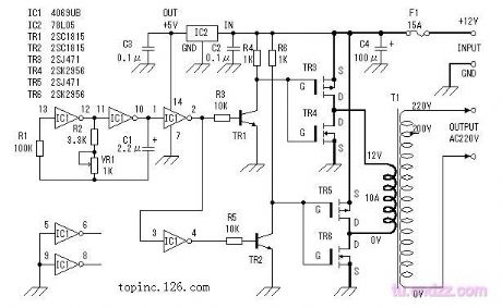
Amateur production inverter circuit application diagram
Published:2011/4/12 0:43:00 Author:Nicole | Keyword: amateur production, inverter
View full Circuit Diagram | Comments | Reading(611)
Amateur precision steady voltage circuit
Published:2011/4/12 0:45:00 Author:Nicole | Keyword: steady voltage
View full Circuit Diagram | Comments | Reading(555)
Remote control turn-off integrated regulated power supply
Published:2011/4/12 0:48:00 Author:Nicole | Keyword: remote control, regulated power supply
View full Circuit Diagram | Comments | Reading(555)
Pocket switch power supply charger circuit BQ2057
Published:2011/4/12 3:12:00 Author:Nicole | Keyword: switch power supply, charger
View full Circuit Diagram | Comments | Reading(896)
Sound control AC voltage regulator circuit
Published:2011/4/12 3:20:00 Author:Nicole | Keyword: sound control, AC voltage regulator
View full Circuit Diagram | Comments | Reading(727)
Parallel regulated power supply composed of LM109
Published:2011/4/12 3:35:00 Author:Nicole | Keyword: regulated power supply
View full Circuit Diagram | Comments | Reading(603)
Trimming bistable regulated power supply composed of LM109, LM120
Published:2011/4/12 3:41:00 Author:Nicole | Keyword: regulated power supply
View full Circuit Diagram | Comments | Reading(541)
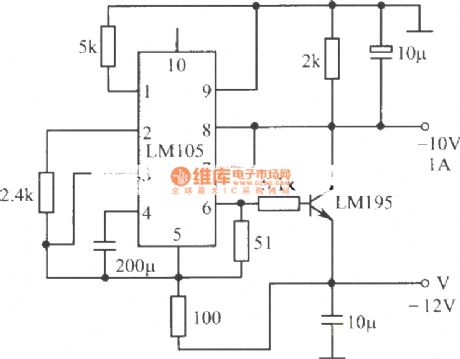
-10V, 1A regulated power supply composed of LM105 integrated regulator, LM195 power transistor
Published:2011/4/12 3:44:00 Author:Nicole | Keyword: regulated power supply, integrated regulator, power transistor
View full Circuit Diagram | Comments | Reading(740)
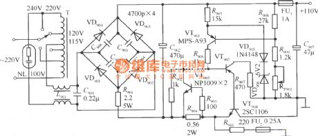
110V regulated power supply
Published:2011/4/12 3:51:00 Author:Nicole | Keyword: regulated power supply
View full Circuit Diagram | Comments | Reading(569)
Micro-power polarity reversal circuit diagram composed of MAX1721
Published:2011/4/2 4:34:00 Author:Nicole | Keyword: Micro-power polarity reversal

As shown, micro-power polarity reversal composed of miniature (SOT23 package) inverting charge pump IC MAX1721. This circuit just need take a 0.33μF little capacity, small size capacitor on the outside of MAX1721, then the polarity reversal can be completed, that is the output voltage Vo =- Vi.
(View)
View full Circuit Diagram | Comments | Reading(744)
| Pages:2117/2234 At 2021012102210321042105210621072108210921102111211221132114211521162117211821192120Under 20 |
Circuit Categories
power supply circuit
Amplifier Circuit
Basic Circuit
LED and Light Circuit
Sensor Circuit
Signal Processing
Electrical Equipment Circuit
Control Circuit
Remote Control Circuit
A/D-D/A Converter Circuit
Audio Circuit
Measuring and Test Circuit
Communication Circuit
Computer-Related Circuit
555 Circuit
Automotive Circuit
Repairing Circuit


