
Circuit Diagram
Index 2118
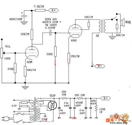
6n3 Tube amplifier power supply circuit diagram
Published:2011/4/2 4:24:00 Author:Nicole | Keyword: Tube amplifier power supply
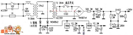
As shown , after the power through switch and inductor, then through T1 transformer, through rectifier filter then supply power to he filament and TDA2822, T2 is connected to the T1 secondary, producing high voltage, the rectifier filter and regulator supply high voltage to 6N3. The signal outputed after amplified by 6N3, then through TDA2822 drive headphone. In this paper, the circuit is simple, without any debugging, the component parameters have been indicated in the schematic, the select of components can refer to other articles, to use some components with better performance. This machine is particularly quiet in the static, sound is very good.
(View)
View full Circuit Diagram | Comments | Reading(2683)
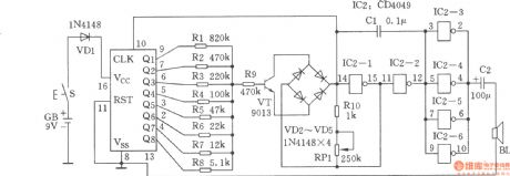
Polyphonic sound imitation generator
Published:2011/4/10 22:33:00 Author:Ecco | Keyword: Polyphonic , sound imitation , generator
View full Circuit Diagram | Comments | Reading(864)
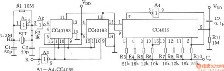
Noise generator composed of CH4040
Published:2011/4/12 0:38:00 Author:Ecco | Keyword: Noise generator

View full Circuit Diagram | Comments | Reading(801)
Wien-bridge sine wave generator 1
Published:2011/4/10 22:42:00 Author:Ecco | Keyword: Wien-bridge , sine wave generator

View full Circuit Diagram | Comments | Reading(660)
Wien-bridge sine wave generator 2
Published:2011/4/10 22:43:00 Author:Ecco | Keyword: Wien-bridge , sine wave generator

View full Circuit Diagram | Comments | Reading(546)
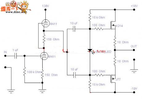
6n11 electron tube power amplifier circuit diagram
Published:2011/4/1 4:03:00 Author:Nicole | Keyword: electron tube
View full Circuit Diagram | Comments | Reading(2601)
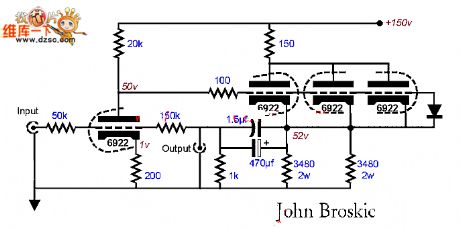
6922 electron tube amp circuit diagram
Published:2011/4/1 4:03:00 Author:Nicole | Keyword: electron tube
View full Circuit Diagram | Comments | Reading(1908)
Wien-bridge sine wave generator 3
Published:2011/4/10 22:45:00 Author:Ecco | Keyword: Wien-bridge, sine wave generator

View full Circuit Diagram | Comments | Reading(1161)
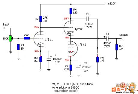
Amp circuit diagram with electron tube e88cc
Published:2011/4/1 4:02:00 Author:Nicole | Keyword: Amp, electron
View full Circuit Diagram | Comments | Reading(4447)
6p6p amp circuit diagram
Published:2011/4/1 4:02:00 Author:Nicole | Keyword: amp
View full Circuit Diagram | Comments | Reading(1494)
DC voltage bidirectional out-of-limit alarm circuit
Published:2011/4/6 4:10:00 Author:Nicole | Keyword: DC voltage, bidirectional out-of-limit

This alarm circuit will issue a directive when the power voltage is higher or lower a range, to remind us to adopt necessary measures. In this circuit, W2, W3 determines the starting value of upper and lower limit alarm. Circuit adjustment can be done by using a regulator.
(View)
View full Circuit Diagram | Comments | Reading(554)
Multi-channel detector circuit
Published:2011/4/12 4:13:00 Author:Nicole | Keyword: detector
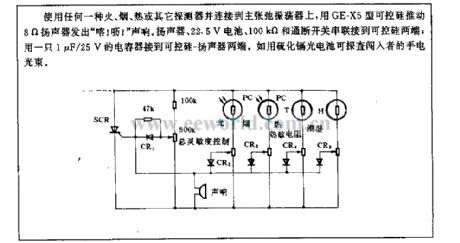
Using any fire, smoke, heat or other detectors and connecting to the primary relaxation oscillator, using GE-X5 thyristor to push 8Ω loudspeaker emits keke . Loudspeaker, 22.5V battery, 100kΩ and on/off switch are in series with the both ends of thyristor; connected a 1μF/25V capacitor to the both ends of thyristor-loudspeaker. Such as using cadmium sulfide photocell can detect the flashlight light beam of interloper. (View)
View full Circuit Diagram | Comments | Reading(920)
AC electric welding machine no-load energy-saving circuit
Published:2011/4/6 4:11:00 Author:Nicole | Keyword: electric welding machine, energy-saving

As shown in the figure, T1 is AC electric welding machine transformer. The power switch HK turns on, power transformer T2 obtains the electricity first, filter capacitor C1 obtains about 12V AC voltage. IC1, IC2 is two 555 time base IC. Because the voltage of initial state C2 is 0, the ②、⑥ pins of IC1 is low level, so ③ pin is high level, relay K is not pull-in, AC contactor KM is not work, electric welding machine is no energizing. At the same time, the multivibrator composed of IC2 starts working, the output frequency of ③ pin is about 10kHz pulse singal. After through R5, the later singal is added to one end of T1 secondary, the other end is connected to the grouding of control circuit, duing to T1 secondary winding has large inductance about 10kHz singal, so the current of this loop is lower, the voltage of transformer L is lower too. the other singal is coupled to C4, after VDR、VD9 rectifiers, C5 filter, the DC voltage turns VT1 on, VT2 off. So C2 is without charge current, IC1③ pin keeps high level. The circuit is in no-load energy-saving state.
(View)
View full Circuit Diagram | Comments | Reading(5579)
Multi-purpose FM signal generator
Published:2011/4/12 2:54:00 Author:Ecco | Keyword: Multi-purpose , FM signal generator

The multi-purpose FM signal generator is shown in the chart. VTl, VT2 form multivibrator, VT3 is emitter follower, which makes a frequency modulation to osicillating signal source of VT4, and sent by Tx antenna.
(View)
View full Circuit Diagram | Comments | Reading(1577)
Pulse width modulation circuit
Published:2011/4/10 22:48:00 Author:Ecco | Keyword: Pulse , width modulation

View full Circuit Diagram | Comments | Reading(763)
Linear pulse width modulation circuit
Published:2011/4/10 22:49:00 Author:Ecco | Keyword: Linear , pulse width modulation

View full Circuit Diagram | Comments | Reading(743)
Frequency shift keying signal (FSK) generator
Published:2011/4/12 3:37:00 Author:Ecco | Keyword: Frequency shift keying, signal generator
View full Circuit Diagram | Comments | Reading(1046)
Sine wave generator circuit(555)
Published:2011/4/12 3:38:00 Author:Ecco | Keyword: Sine wave generator , 555

View full Circuit Diagram | Comments | Reading(4746)
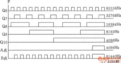
60Hz frequency source
Published:2011/4/12 3:33:00 Author:Ecco | Keyword: 60Hz, frequency source
View full Circuit Diagram | Comments | Reading(397)
Laser transmitter linearity control circuit
Published:2011/4/6 4:11:00 Author:Nicole | Keyword: laser transmitter, linearity control
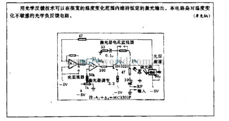
Used optical feedback technique can keep constant laser output in a wide temperature range. This circuit is a optical negative feedback circuit which is insensitive to temperature.
(View)
View full Circuit Diagram | Comments | Reading(580)
| Pages:2118/2234 At 2021012102210321042105210621072108210921102111211221132114211521162117211821192120Under 20 |
Circuit Categories
power supply circuit
Amplifier Circuit
Basic Circuit
LED and Light Circuit
Sensor Circuit
Signal Processing
Electrical Equipment Circuit
Control Circuit
Remote Control Circuit
A/D-D/A Converter Circuit
Audio Circuit
Measuring and Test Circuit
Communication Circuit
Computer-Related Circuit
555 Circuit
Automotive Circuit
Repairing Circuit