
Circuit Diagram
Index 2116
Ultrasonic whistle remote control fan speed regulation with sound waves circuit diagram
Published:2011/4/6 1:57:00 Author:Rebekka | Keyword: Ultrasonic whistle, remote control fan , speed regulation with sound waves

Circuit is shown as below. it includes two parts, ultrasonic sound flute and Asia ultrasound receive/control circuits. Ultrasonic whistle can remote control the speed of electric fan. The features are: Convenient operation, strong anti-interference etc. The circuit will give a cool simulation sound of the waves. (View)
View full Circuit Diagram | Comments | Reading(1502)
Pyroelectric infrared sensor socket with analog voice circuit diagram(BISS0001)
Published:2011/4/6 3:02:00 Author:Rebekka | Keyword: Pyroelectric infrared sensor socket

Here is the schematic diagram of the circuit. It consists of pyroelectric infrared sensor, infrared signal processing circuit, relay control socket circuits, analog voice circuits and AC step-down rectifier circuit. When someone walk into the venue of pyroelectric infrared surveillance, the socket will be energized and the electrical equipment will be started; At the same time, analog voice circuits will be audible. (View)
View full Circuit Diagram | Comments | Reading(3955)
Simple silicon-controlled dimmer circuit diagram
Published:2011/4/5 21:46:00 Author:Ecco | Keyword: Simple silicon-controlled , dimmer

Simple silicon-controlled dimmer
As shown in Figure 13, it is a simple circuit of SCR dimming lights. The w resistance in the potentiometer decreases, SCR conduction angle increases, the light's intensity increases, the resistance enlarges, the SCR conduction angle decreases, the light's intensity decreased. It can also be used as adjusting the heating temperature.
(View)
View full Circuit Diagram | Comments | Reading(2820)
Simple music control lights circuit diagram
Published:2011/4/5 21:17:00 Author:Ecco | Keyword: Simple music , control light

Simple music control lights circuit
It connects according to the chart 40, The audio voltage with the partial pressure can trigger bidirectional triode thyristor by transformer, the strength of the lamp changes alternately according to the music signal light, when using, the potentiometer can be connected directly to the tape recorder speaker at both ends.
(View)
View full Circuit Diagram | Comments | Reading(1258)
Two 110-volt light bulbs connected to the 220-volt power supply circuit
Published:2011/4/6 1:47:00 Author:Ecco | Keyword: 110-volt light bulb, 220-volt power supply

Two 110-volt light bulbs connected to the 220-volt power
The power supply in some areas is 110V while the majority of the power supply in majority of areas is 220V, as shown in Figure 8, two 110V bulbs can be connected to the 220V power supply in series connection. Note: The power of two 110V lamps must be the same, otherwise, the smaller power bulb will be burnt earsily.
(View)
View full Circuit Diagram | Comments | Reading(1965)
The fluorescent with reactive power compensation circuit diagram
Published:2011/4/6 2:20:00 Author:Ecco | Keyword: fluorescent , reactive power compensation

The fluorescent with reactive power compensation
As ballast is an inductive load. It needs to consume some reactive power, causing the power factor of fluorescent lamp decreases. It affects the ability of full-powered devices, and reduces the voltage of power stations, and it's harmful to saving electricity. In order to improve power factor, where the using of fluorescent lamps, fluorescent lamp power supply side should be parallel connected a capacitor, so that the ballast's reactive power can be provided by capacitor. Figure 25 shows. The size of capacitor and fluorescent power is related. Fluorescent power is 15 ~ 20W, matching capacitance is 2.5μF; fluorescent power is 30w, the optional capacitance is 3.75μF; fluorescent power is 40w, the optional capacitance is 4.75μF. The optional capacitor voltage are 400V.
(View)
View full Circuit Diagram | Comments | Reading(1560)
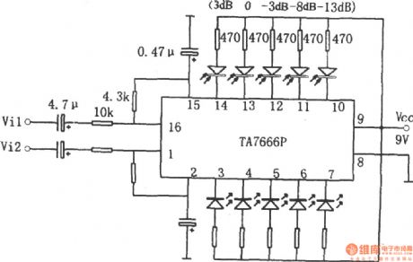
TA7666P dual five LED level display driving circuit
Published:2011/4/6 20:38:00 Author:Ecco | Keyword: dual five , LED level , display driving
View full Circuit Diagram | Comments | Reading(4807)
Infrared remote control delay light switch circuit diagram
Published:2011/4/12 4:28:00 Author:Rebekka | Keyword: infrared remote control

\
The circuit consists of infrared receiver, one-shot delay circuit and the silicon components (View)
View full Circuit Diagram | Comments | Reading(1370)
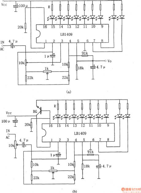
LB1409 nine LED level display driver circuit
Published:2011/4/6 20:17:00 Author:Ecco | Keyword: nine LED , level display , driver circuit
View full Circuit Diagram | Comments | Reading(1969)
Reflection type light delay switch circuit diagram
Published:2011/4/12 4:26:00 Author:Rebekka | Keyword: Reflection type light delay switch

TX05D is a low power infrared reflection switch control components. (View)
View full Circuit Diagram | Comments | Reading(638)
Reflection type infrared control circuit diagram
Published:2011/4/12 4:25:00 Author:Rebekka | Keyword: Reflection type infrared control

View full Circuit Diagram | Comments | Reading(368)
Using tone decoder infrared remote control circuit diagram
Published:2011/4/12 4:23:00 Author:Rebekka | Keyword: tone decoder, infrared remote control


Eight-channel remote control transmitter:
Receiving, voltage amplification, decoding circuit:
(View)
View full Circuit Diagram | Comments | Reading(1335)
Using audio coding wireless alarm system circuit diagram
Published:2011/4/12 4:20:00 Author:Rebekka | Keyword: audio coding wireless alarm system

Figure(A) shows the launch of the system circuit.Figure(B) shows the receiver circuit of the system. (View)
View full Circuit Diagram | Comments | Reading(840)
Common infrared remote control code and decoding circuit diagram
Published:2011/4/12 4:18:00 Author:Rebekka | Keyword: Common infrared remote control

View full Circuit Diagram | Comments | Reading(415)
ZH9576 internal circuit and pinout function circuit diagram
Published:2011/4/12 4:17:00 Author:Rebekka | Keyword: internal circuit , pinout function circuit

ZH9576 is infrared control circuit that composed of a set of infrared emission, infrared receiver demodulation and control output as a whole. (View)
View full Circuit Diagram | Comments | Reading(467)
μPC1373H and LA7224 internal circuit and pinout circuit diagram
Published:2011/4/12 4:14:00 Author:Rebekka | Keyword: internal circuit , pinout circuit

View full Circuit Diagram | Comments | Reading(417)
Special sound audio oscillator circuit(NE555、CD4017)
Published:2011/4/6 20:12:00 Author:Ecco | Keyword: Special sound , audio oscillator

View full Circuit Diagram | Comments | Reading(3110)
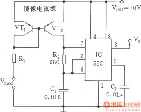
Linear voltage-controlled oscillator(555)
Published:2011/4/10 22:13:00 Author:Ecco | Keyword: Linear , voltage-controlled oscillator, 555
View full Circuit Diagram | Comments | Reading(942)
KD9562 Eight analog sound circuit
Published:2011/4/12 4:11:00 Author:Rebekka | Keyword: Eight analog sound


Expanded to 32 analog voice:
(View)
View full Circuit Diagram | Comments | Reading(455)
LC2200 internal circuit and application circuit diagram
Published:2011/4/12 4:10:00 Author:Rebekka | Keyword: internal circuit , application circuit

Channel decoding circuit LC2200 is an improved IC of LC220. LC2200 internal circuit and application circuit diagram is shown as above. (View)
View full Circuit Diagram | Comments | Reading(757)
| Pages:2116/2234 At 2021012102210321042105210621072108210921102111211221132114211521162117211821192120Under 20 |
Circuit Categories
power supply circuit
Amplifier Circuit
Basic Circuit
LED and Light Circuit
Sensor Circuit
Signal Processing
Electrical Equipment Circuit
Control Circuit
Remote Control Circuit
A/D-D/A Converter Circuit
Audio Circuit
Measuring and Test Circuit
Communication Circuit
Computer-Related Circuit
555 Circuit
Automotive Circuit
Repairing Circuit