
Circuit Diagram
Index 2101
The separate excitation crossover multivibrator
Published:2011/4/14 2:39:00 Author:Ecco | Keyword: separate excitation, crossover, multivibrator

The separate excitation crossover multivibrator is shown in the chart. It has two or four types of split-phase output waveform, and can easily obtain 0°,-90°,-180°, 270°split-phase square wave. It has the features of simple structure, good output waveform, eliminating the traditional frequency, counting, decoding circuit. It should be used in the phase generator, four-cycle water lantern controller circuit,etc.
(View)
View full Circuit Diagram | Comments | Reading(611)
The separate excitation crossover oscillator used in four recirculating water lantern controller
Published:2011/4/14 2:40:00 Author:Ecco | Keyword: separate excitation rossover oscillator, four recirculating , water lantern , controller
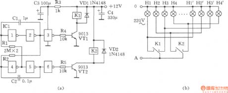
The figure shows the separate excitation crossover oscillator used in four recirculating water lantern controller, the circuit only adopts two sets of contactrelay 4088 to control the four water lanterns. The working principle: the six NOT gate CD4069 in ICl and C1, C2, Rl, R2 form the separate excitation crossover oscillator circuit, it controls the transistor VTl, VT2 directly and drives relays Kl, K2 for the cross-phase output, that is the after Kl pulls, then K2 pulls, and Kl disconnects, K2 then disconnects and go in the cycle. (B) shows the lantern connection diagram.
(View)
View full Circuit Diagram | Comments | Reading(536)
The stable function generator
Published:2011/4/14 2:32:00 Author:Ecco | Keyword: stable, function generator
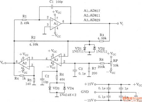
This circuit is a function generator, as shown. Its square-wave output has a short rise time and the amplitude is not sensitive to temperature; In addition,thetriangular output waveform changesat the exactlysame rate in the whole range.
(View)
View full Circuit Diagram | Comments | Reading(743)
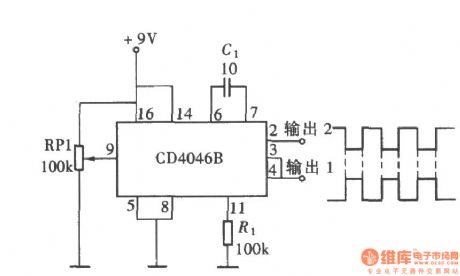
The opposite phase symmetric square wave produced by CD4046
Published:2011/4/14 2:31:00 Author:Ecco | Keyword: opposite phase , symmetric , square wave
View full Circuit Diagram | Comments | Reading(1632)
2~35V、10A adjustable regulated power supply composed of MPC1000
Published:2011/4/13 3:39:00 Author:Nicole | Keyword: regulated power supply

View full Circuit Diagram | Comments | Reading(493)
±15V、10A symmetric regulated power supply composed of MPC1000
Published:2011/4/13 3:41:00 Author:Nicole | Keyword: regulated power supply

View full Circuit Diagram | Comments | Reading(1792)
±5V and ±l2V regulated power supply composed of MPC1000, LM320 and used in computer
Published:2011/4/13 3:44:00 Author:Nicole | Keyword: regulated power supply, computer

View full Circuit Diagram | Comments | Reading(825)
AC purification regulated power supply circuit
Published:2011/4/14 2:32:00 Author:Nicole | Keyword: AC purification, regulated power supply
AC purification regulated power supply circuit (View)
View full Circuit Diagram | Comments | Reading(427)
NC monostable multivibrator circuit
Published:2011/4/14 2:40:00 Author:Ecco | Keyword: NC, monostable , multivibrator

The NC monostable multivibrator circuit shown in the chart is composed of four 2 input NOR gate CC4001 and 14-bit binary serial counter / divider CC4020. It mainly used as time delay switch or timer in automatic control equipments. (View)
View full Circuit Diagram | Comments | Reading(1727)
Yiyou BCD - 170 refrigerator
Published:2011/4/13 4:31:00 Author:Ecco | Keyword: Yiyou , refrigerator

View full Circuit Diagram | Comments | Reading(490)
Homemade gunfire analog generator
Published:2011/4/14 2:45:00 Author:Ecco | Keyword: Homemade gunfire , analog generator

Two transistors form a complementary audio oscillator which could be used as gunfire analog sound generator, and the sounds are realistic, rich in reverberation. The circuit is as shown. Selection of components: transistor VTl, VT2: 9014, β = 85 ~ 115, VT3, VT4: 9015, β = 65 ~ 85. Sl: AN4, S2: KN3. LED VDl ~ VD6: BT201, can also choose other models, the best selection is the LED in low power, high luminous efficiency. Battery GB: 4F22DC6V stacked batteries. Speaker BL: 8Ω, 0.25W.
(View)
View full Circuit Diagram | Comments | Reading(1375)
Rain generator composed of NE555
Published:2011/4/14 2:45:00 Author:Ecco | Keyword: Rain generator

This circuit is very simple, it's composed of regular component, which includes two oscillators, one is a frequency oscillator of single-junction transistors VTl (2N2646) variable, VTl can oscillate without resonant coils, the circuit is shown in the chart.
(View)
View full Circuit Diagram | Comments | Reading(2031)
Simple seashore generator
Published:2011/4/14 2:46:00 Author:Ecco | Keyword: Simple, seashore generator

View full Circuit Diagram | Comments | Reading(830)
24V CRT high voltage power supply circuit diagram
Published:2011/4/14 2:42:00 Author:Ecco | Keyword: 24V, CRT, high voltage, power supply

Some cameras use 11.4cm (4.5 inches) pure flat CRT as the display component, the anode voltage of high-voltage components is +20 kV, focus electrode voltage is +3.2 kV, accelerating voltage is +1000 V, the power supply of high voltage components is DC in 24V. It's as the chart shown:
Basic principles: NE555 constitutes pulse generator, to adjust potentiometer VR2 can generate a pulse with the frequency in about 20kHz, potentiometer VR1 adjusts the pulse width. TR1 is driver stage, the pulse transformer T1 adopts reverse polarity excitation, that is TR1 being on while TR2 being off, TR2 being on while TR1 being off, D3, C9, VR3, R7 and D4, R6, TR3 form a high-voltage protection circuit. VR2 is used for adjusting the frequency, and VR2 is used for adjusting the size of high voltage.
VR2 uses precision adjustable resistors. T2 can adopt colour TV line output transformer. The writer uses the Toyo SE-1438G Series of 35cm (14 inch) color TV line output transformer, with the anode voltage up to 20kV, and then choose the resistance of R8 to make acceleration voltage be +1000 V, the resistance of R9 make the focus electrode voltage be +3.2 kV. The whole part is packaged with aluminum box, aluminum jacket is connected to the earth to reduce the interference on the circuit.
(View)
View full Circuit Diagram | Comments | Reading(4780)
Using large capacitor C to instead back up battery circuit
Published:2011/4/13 3:09:00 Author:Nicole | Keyword: large capacitor C, back up battery

View full Circuit Diagram | Comments | Reading(609)
PIC16C72 and X9241 interface circuit
Published:2011/4/13 3:47:00 Author:Nicole | Keyword: interface

View full Circuit Diagram | Comments | Reading(927)
MAXl898 single node Li + battery linear charger
Published:2011/4/13 3:57:00 Author:Nicole | Keyword: single node Li, battery linear charger

View full Circuit Diagram | Comments | Reading(483)
MAX846A most typical application circuit charging circuit
Published:2011/4/13 4:01:00 Author:Nicole | Keyword: charging

In figure, MAX846A is as a free limit voltage current source to charge to lithium ion battery.
(View)
View full Circuit Diagram | Comments | Reading(533)
LS7232 internal circuit and pinout array
Published:2011/4/14 1:58:00 Author:Rebekka | Keyword: internal circuit , pinout array

View full Circuit Diagram | Comments | Reading(434)
LC2210 typical application circuit diagram
Published:2011/4/14 1:59:00 Author:Rebekka | Keyword: typical application

View full Circuit Diagram | Comments | Reading(417)
| Pages:2101/2234 At 2021012102210321042105210621072108210921102111211221132114211521162117211821192120Under 20 |
Circuit Categories
power supply circuit
Amplifier Circuit
Basic Circuit
LED and Light Circuit
Sensor Circuit
Signal Processing
Electrical Equipment Circuit
Control Circuit
Remote Control Circuit
A/D-D/A Converter Circuit
Audio Circuit
Measuring and Test Circuit
Communication Circuit
Computer-Related Circuit
555 Circuit
Automotive Circuit
Repairing Circuit