
Circuit Diagram
Index 2113
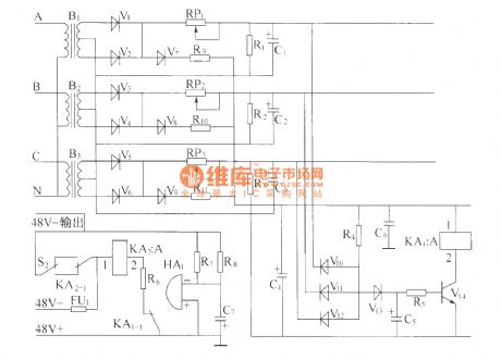
AC distribution unit monitoring alarm circuit(P50-II)
Published:2011/3/23 21:18:00 Author:muriel | Keyword: AC distribution unit, monitoring alarm circuit, P50-II
View full Circuit Diagram | Comments | Reading(606)
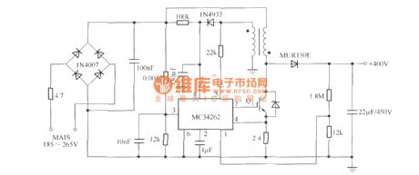
Low cost power factor correcting circuit with IGBT switch
Published:2011/3/23 21:26:00 Author:muriel | Keyword: Low cost, power factor, correcting circuit, IGBT switch, MC34262
View full Circuit Diagram | Comments | Reading(1184)
Low cost CFL electronic ballast circuit with IGBT switch
Published:2011/3/23 21:27:00 Author:muriel | Keyword: Low cost , CFL electronic ballast circuit, IGBT switch, MUR180

View full Circuit Diagram | Comments | Reading(3237)
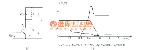
IGBT turn-off voltage waveform in the hard switching chopper circuit
Published:2011/3/23 21:29:00 Author:muriel | Keyword: IGBT , turn-off voltage waveform, hard switching , chopper circuit
View full Circuit Diagram | Comments | Reading(1380)
Crystal diode STTH60L06TV2 and STTH6110TV2 internal circuit diagram
Published:2011/4/12 22:55:00 Author:Rebekka | Keyword: Crystal diode

Crystal diode STTH60L06TV2 and STTH6110TV2 internal circuit diagram is shown as above. (View)
View full Circuit Diagram | Comments | Reading(572)
CMos drive circuit for LCD
Published:2011/4/12 22:52:00 Author:Rebekka | Keyword: CMos drive circuit
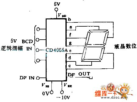
CD4054 A, CD4055A or CD4056A CMOS direct drive 7 LCD display digit.The circuit has the feature of internal level shift. The feature is to change 5V logical rotation to state-driven consumption LCD. It is integrant for 30V peak AC signal used by the LCD.
(View)
View full Circuit Diagram | Comments | Reading(912)
Bypass switch with IGBT
Published:2011/3/23 21:37:00 Author:muriel | Keyword: Bypass switch, IGBT

View full Circuit Diagram | Comments | Reading(579)
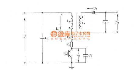
QRC Soft Switching flyback converter schematic diagram
Published:2011/3/23 21:44:00 Author:muriel | Keyword: QRC , Soft Switching, flyback converter , schematic diagram
View full Circuit Diagram | Comments | Reading(1080)
IF HVPS PWM circuit
Published:2011/3/23 21:48:00 Author:muriel | Keyword: IF, HVPS , PWM circuit, SG3524, PM10CSJ060
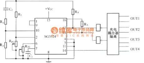
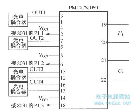
The connection of PWM signal and IPM intelligent power module PM10CSJ060 :
(View)
View full Circuit Diagram | Comments | Reading(816)
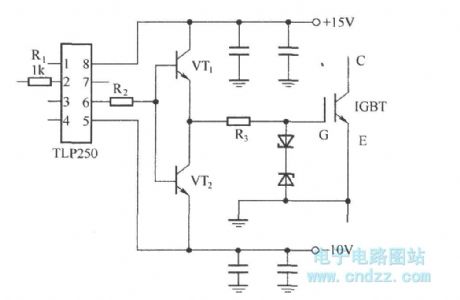
Driver with integrated circuit TLP250
Published:2011/3/23 21:49:00 Author:muriel | Keyword: Driver , integrated circuit, TLP250
View full Circuit Diagram | Comments | Reading(8893)
IGBT drive circuit with discrete component
Published:2011/3/23 21:50:00 Author:muriel | Keyword: IGBT , drive circuit, discrete component, TLP560

View full Circuit Diagram | Comments | Reading(2989)
Active clamped RDCLI power circuit
Published:2011/3/23 21:56:00 Author:muriel | Keyword: Active , clamped, RDCLI , power circuit

View full Circuit Diagram | Comments | Reading(553)
The multivibrator composed of CD4017
Published:2011/4/13 2:17:00 Author:Ecco | Keyword: multivibrator
View full Circuit Diagram | Comments | Reading(614)
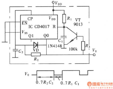
The pulse generator with adjustable duty cycle and frequency
Published:2011/4/13 2:15:00 Author:Ecco | Keyword: pulse generator w, adjustable duty cycle , adjustable frequency

View full Circuit Diagram | Comments | Reading(3094)
Pulse width controllable pulse generator composed of CC4516
Published:2011/4/13 2:14:00 Author:Ecco | Keyword: Pulse width, controllable , pulse generator

View full Circuit Diagram | Comments | Reading(652)
Simple pulse signal generator composed of 74LS00、74LS221
Published:2011/4/13 2:12:00 Author:Ecco | Keyword: Simple , pulse signal generator

The simple pulse generator circuit is shown as the chart. The pulse generator mainly adopts two TTL signal generator IC (74LS00 and 74LS221) to generte the τ = 4μs pulse signal, it uses fewer components, so it's easy to do debugging and maintenance.
(View)
View full Circuit Diagram | Comments | Reading(2092)
Self-control digital inverter power supply circuit diagram:1.2V rising to 9V
Published:2011/4/13 2:05:00 Author:Ecco | Keyword: Self-control, digital inverter, power supply

It does not require the establishment of a separate power switch or transformation to switches in the table. The circuit has the advantages of low power consumption, stability and reliability, no effect on instrument accuracy and so on. The transformer T in the circuit is E3-type core, to cut off each corner and process to be the mouth shape, L2 is inside while LJ is outside. When the inverter power supply works, the battery current is about 70mA. As shown in the chart:
(View)
View full Circuit Diagram | Comments | Reading(2506)
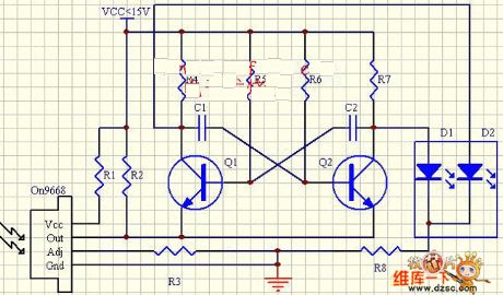
Light control LED flashing circuit diagram
Published:2011/4/12 22:44:00 Author:Rebekka | Keyword: Light control LED flashing
View full Circuit Diagram | Comments | Reading(531)
4 Direct drive LCD display circuit diagram
Published:2011/4/12 22:42:00 Author:Rebekka | Keyword: Direct drive LCD display

Each part of LCD has individual counter, latch, decoder and driver. Pumping signal feeds back to the motherboard of LCD. When the display section is disconnected, the phase and amplitude of the motherboard and display segment drive signal are the same. It shows no voltage on the 2 ends of display. When the display segment is triggered, its pumping signal phase position will be lager than 180 °, so the square wave voltage is 2 times than power supply voltage value. BCD code input signal can be produced from the dual BCD counter of cascade MC14518.
(View)
View full Circuit Diagram | Comments | Reading(1605)
LC square wave generator
Published:2011/4/13 1:50:00 Author:Ecco | Keyword: LC , square wave , generator

Square-wave generator with LC circuit can get a better frequency stability, it's as shown in the chart. This three-terminal oscillator of capacitor can be used to generate a square wave, but an operational amplifier is used as the active component.
(View)
View full Circuit Diagram | Comments | Reading(2372)
| Pages:2113/2234 At 2021012102210321042105210621072108210921102111211221132114211521162117211821192120Under 20 |
Circuit Categories
power supply circuit
Amplifier Circuit
Basic Circuit
LED and Light Circuit
Sensor Circuit
Signal Processing
Electrical Equipment Circuit
Control Circuit
Remote Control Circuit
A/D-D/A Converter Circuit
Audio Circuit
Measuring and Test Circuit
Communication Circuit
Computer-Related Circuit
555 Circuit
Automotive Circuit
Repairing Circuit