
Circuit Diagram
Index 2100
28V、1A regulated power supply composed of SN52105
Published:2011/4/14 3:22:00 Author:Nicole | Keyword: regulated power supply

View full Circuit Diagram | Comments | Reading(542)
15V、300mA regulated power supply composed of SN52105
Published:2011/4/14 3:23:00 Author:Nicole | Keyword: regulated power supply

View full Circuit Diagram | Comments | Reading(526)
Discrete device multifunction charger schematic diagram
Published:2011/4/13 22:55:00 Author:Nicole | Keyword: discrete device, multifunction charger
Discrete device multifunction charger is composed of reference voltage source, constant voltage and constant current source, voltage detection circuit, highest battery temperature, detection circuit and discharge circuit, as shown in the figure. (View)
View full Circuit Diagram | Comments | Reading(457)
Symmetric steady voltage circuit
Published:2011/4/13 22:37:00 Author:Nicole | Keyword: symmetric steady voltage

Adopting butted amplitude limiter circuit composed of regulator tube, if you want to have symmetry, it needs two regulator tubes with same performance, such as this oscilloscope circuit, but it is hard to achieve in practice. So we can connect regulator tubes to rectifier DC circuit(figure a), output voltage UA is the sum of two diodes forward voltage drop UD2, UD5 or UD4, UD3 and regulator tube work voltage UZ. That is, +UA=UD2+UZ+UD5 or - UA=UD3+UZ+UD4. To select regulator tube work voltage and work point appropriately, it also can achieve temperature compensation for output voltage.
The figure (b) is large current amplitude limiter circuit. In the positive half cycle, the base-collector junction diode of transistor T1 is equal to diode D2 in figure(a), the base-emitter junction diode of T2 in series with diode D3 are equal to diode D5 in figure(a). (View)
View full Circuit Diagram | Comments | Reading(512)
Loss pulse alarm circuit
Published:2011/4/13 21:25:00 Author:Nicole | Keyword: Loss pulse, alarm

This circuit is used to test missing light pulse or the shortages of goods in sport transport tape. CA3062 combined photodetector and amplifier, it can test the light pulse which is synchronous with 60Hz power supply frequency. When switch SW1 is in A, each pulse is as 16.7ms interval to reset the 20ms timing network of 2N2646 unijunction transistor, to prevent unijunction transistor from triggering, and to trigger 2N2529 SCR turn on alertor. When SW1 is in B, this circuit interrupts detection steady light beam, the alertor alarms only in the case of without interruption. (View)
View full Circuit Diagram | Comments | Reading(697)
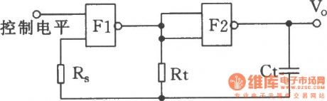
The controlled oscillator composed of Nand gate
Published:2011/4/7 3:32:00 Author:Ecco | Keyword: controlled oscillator, NOT gate
View full Circuit Diagram | Comments | Reading(543)
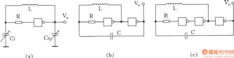
LC oscillator composed of NAND gate
Published:2011/4/7 3:32:00 Author:Ecco | Keyword: LC oscillator , NAND gate
View full Circuit Diagram | Comments | Reading(1489)
Wien oscillator regulator
Published:2011/4/14 2:52:00 Author:Ecco | Keyword: wien , oscillator , regulator
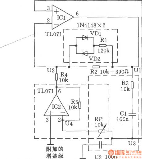
In the Wien bridge, to change any resistance will change the frequency and attenuation. As shown, by adjusting the resistance can change the gain of the amplifier and compensate for the attenuation.
(View)
View full Circuit Diagram | Comments | Reading(526)
USW-B ultrashort wave electrizer circuit
Published:2011/4/14 1:54:00 Author:Ecco | Keyword: USW-B, ultrashort wave , electrizer circuit

View full Circuit Diagram | Comments | Reading(774)
LED tune indication circuit
Published:2011/4/7 23:06:00 Author:Nicole | Keyword: LED, tune indicating

Connecting a LED to each endpoint of tune disk. If one of LEDs turns on, tune indication will depart from it and remove, when two LEDs are all off, it will move to dead point, then it can obtain true tuning point.
The advantage of this tuner is minimum current consumption, even using a very weak LED, it also can indicate tiny mistaken tuning. To adjust VR1, broaden tuning point zone enough, then LED will not flashing because of the loud language or music. (View)
View full Circuit Diagram | Comments | Reading(512)
LG electronics MS-5586DTM computerized grill microwave circuit
Published:2011/4/14 3:06:00 Author:Ecco | Keyword: LG , electronics, computerized, grill , microwave circuit

View full Circuit Diagram | Comments | Reading(638)
LG electronics MS-1977MT computerized microwave circuit
Published:2011/4/14 3:06:00 Author:Ecco | Keyword: LG , electronics, computerized , microwave circuit

View full Circuit Diagram | Comments | Reading(740)
LG electronics MS-2576T, MS-2586T mechanical microwave circuit
Published:2011/4/14 3:06:00 Author:Ecco | Keyword: LG , electronics , mechanical, microwave circuit

View full Circuit Diagram | Comments | Reading(970)
LG electronics MS - 2576MT computerized microwave circuit
Published:2011/4/14 3:06:00 Author:Ecco | Keyword: LG , electronics , computerized , microwave circuit

View full Circuit Diagram | Comments | Reading(1652)
LED slow charge circuit
Published:2011/4/6 22:49:00 Author:Nicole | Keyword: LED, charge

LED uses NSL4944 which produced by National Semiconductor Company, it has the characteristics of constant current. After input AC power supply, and through half wave rectification charging circuit, it can charge to 1.5~6.0V battery slowly. (View)
View full Circuit Diagram | Comments | Reading(545)
The special linear regulated power supply composed of 7805,7905,7812
Published:2011/4/14 2:56:00 Author:Ecco | Keyword: linear power supply

As the chart shown: it's a special power supply circuit. The circuit is simple, but it can generate three sets of DC voltagethe by two same secondary windings: +5 V,-5V and +12 V. Its characteristics are: D2, D3 are crossing over the two AC power groups E2 and E3, to play the role of full-wave rectifier.
(View)
View full Circuit Diagram | Comments | Reading(2959)
LED display TTL level circuit
Published:2011/4/6 22:42:00 Author:Nicole | Keyword: LED, TTL level

When there is no cathode ray oscillograph, you can use this circuit to observe TTL level. 74123 integrated circuit contains two retrigger monostable multivibrators with reset input terminals, they are marked for A1 and A2. When the input level changes, LED is lighted up by two monostable multivibrators. Because monostable delays pulse width, so, even the input pulse is narrow, the naked eye still can distinguish the light and dark change of LED. The attached list explains the meaning of three LEDS in various point. (View)
View full Circuit Diagram | Comments | Reading(2068)
Feiyue WP-600 computerized microwave circuit
Published:2011/4/14 3:05:00 Author:Ecco | Keyword: Feiyue , computerized , microwave circuit

View full Circuit Diagram | Comments | Reading(618)
Adjacent pulse and other delay circuits (555)
Published:2011/4/14 2:37:00 Author:Ecco | Keyword: Adjacent pulse , delay circuit, 555

View full Circuit Diagram | Comments | Reading(619)
Simple multi-harmonic generator
Published:2011/4/14 2:39:00 Author:Ecco | Keyword: Simple , multi-harmonic generator
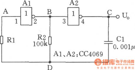
Thecircuit shown in the chart is a multi-harmonic generator circuit which is comprised of hex inverter CC4069 and so on. The circuit is suitable for low-frequency clock oscillation circuit which are less strict for frequency stability and accuracy. (View)
View full Circuit Diagram | Comments | Reading(581)
| Pages:2100/2234 At 2020812082208320842085208620872088208920902091209220932094209520962097209820992100Under 20 |
Circuit Categories
power supply circuit
Amplifier Circuit
Basic Circuit
LED and Light Circuit
Sensor Circuit
Signal Processing
Electrical Equipment Circuit
Control Circuit
Remote Control Circuit
A/D-D/A Converter Circuit
Audio Circuit
Measuring and Test Circuit
Communication Circuit
Computer-Related Circuit
555 Circuit
Automotive Circuit
Repairing Circuit